


UART Communication Protocol Explained for Embedded Systems

Table Of Contents
UART (Universal Asynchronous Receiver/Transmitter) is one of the most fundamental and widely used communication protocols in embedded systems. Despite being decades old, it remains the go-to choice for simple serial communication between microcontrollers and peripheral devices. Understanding UART is essential for any embedded developer.
What is UART?
UART is a hardware communication protocol that enables asynchronous serial communication between two devices. Unlike synchronous protocols (SPI, I2C), UART does not require a shared clock signal. Instead, both devices agree on a predetermined baud rate (bits per second) before communication begins.
The key characteristics of UART include:
- Asynchronous: No clock line needed between devices
- Full-duplex: Can transmit and receive simultaneously
- Point-to-point: Connects exactly two devices
- Variable baud rates: Typically 9600, 19200, 38400, 57600, 115200 bps
How UART Works
Data Frame Structure
Each UART transmission consists of a data frame with the following components:
- Start bit: A single low bit (0) to indicate the beginning of transmission
- Data bits: Typically 5 to 9 bits (8 bits is most common)
- Parity bit (optional): Used for error detection (even, odd, or none)
- Stop bits: One or two high bits (1) to indicate the end of the frame
The most common configuration is 8N1 (8 data bits, no parity, 1 stop bit).
Transmission Process
When transmitting the byte 0x55 (binary 01010101), the UART line transitions as follows:
- Idle state: Logic high (1)
- Start bit: Logic low (0) for 1 bit time
- Data bits: 01010101 (LSB first)
- Stop bit: Logic high (1) for 1 bit time
- Return to idle: Logic high (1)
The receiving UART samples the line at the agreed baud rate, synchronizing on the falling edge of the start bit.
Hardware Connection
UART requires only two wires between devices:
- TX (Transmit): Output from the sender, connected to RX of the receiver
- RX (Receive): Input to the receiver, connected to TX of the sender
- GND (Ground): Common ground reference (essential for voltage compatibility)
Many microcontrollers include additional signals like RTS (Request to Send) and CTS (Clear to Send) for hardware flow control, but these are optional.
Voltage Levels and Logic
UART voltage levels depend on the devices involved:
- TTL (Transistor-Transistor Logic): 0V for logic 0, 3.3V or 5V for logic 1
- RS-232: -3V to -25V for logic 1, +3V to +25V for logic 0 (inverted!)
- RS-485: Differential signaling for noise immunity in industrial environments
When connecting devices with different voltage levels, always use a level shifter or voltage divider to prevent damage.
Common Applications in Embedded Systems
UART is used extensively in embedded development:
- Debugging: Most microcontrollers provide a UART debug interface
- GPS modules: NMEA sentences are transmitted via UART
- Bluetooth modules: HC-05/HC-06 communicate over UART
- WiFi modules: ESP8266 and ESP32 use UART for AT commands
- PC communication: USB-to-Serial adapters for computer interface
Advantages and Limitations
Advantages
- Simple hardware (just two wires plus ground)
- No clock synchronization required
- Widely supported by virtually all microcontrollers
- Minimal protocol overhead
Limitations
- Limited speed compared to SPI
- Only supports point-to-point communication
- No built-in addressing (requires higher-layer protocol for multiple devices)
- Asynchronous nature can cause framing errors
Practical Example
Here’s how to initialize UART on an STM32 microcontroller (pseudocode):
// Configure UART at 115200 baud, 8N1UART_Config config;config.baudrate = 115200;config.wordLength = 8;config.parity = NONE;config.stopBits = 1;UART_Init(UART1, &config);// Transmit a stringconst char *message = "Hello, World!\r\n";UART_Transmit(UART1, message, strlen(message), 1000);// Receive a byteuint8_t received;UART_Receive(UART1, &received, 1, 1000);
Conclusion
UART remains a cornerstone of embedded communication due to its simplicity and versatility. While newer protocols offer higher speeds or more features, UART’s ease of use ensures it will continue to be a fundamental tool in embedded systems development for years to come.
Master UART, and you’ll have a reliable skill for debugging, communicating with peripherals, and building more complex embedded systems.
Previous Article
RTOS Concepts - Tasks, Semaphores, and MutexesNext Article
Pointers and Memory Management in Embedded CRelated Posts

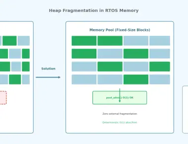
RTOS Concepts - Tasks, Semaphores, and Mutexes
May 09, 2026
3 min

Understanding the volatile Keyword in Embedded C
May 08, 2026
3 min

C Program to implement custom mutex_lock() and mutex_unlock()
September 07, 2025
1 min
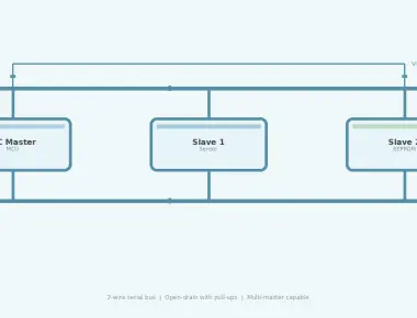
I2C Protocol Deep Dive for Embedded Systems
June 15, 2026
5 min
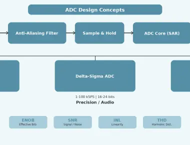
ADC Design Concepts for Embedded Systems
June 14, 2026
5 min
Quick Links
Legal Stuff