

Zephyr Workqueue API for Deferred Work in Embedded Systems
September 27, 2026
6 min
ARM Cortex-M processors achieve deterministic, low-latency interrupt handling through the Nested Vectored Interrupt Controller (NVIC) and a set of hardware optimizations: tail chaining, late arrival, and pop pre-emption. Understanding these mechanisms — and how to configure NVIC priority grouping, BASEPRI, PRIMASK, and FAULTMASK — is essential for writing deterministic RTOS kernels and time-critical firmware.
The NVIC implements a flexible priority scheme supporting up to 256 priority levels (8 bits), though silicon vendors typically implement 3–8 bits. Lower numerical values indicate higher priority. Each interrupt has an 8-bit priority field in the Interrupt Priority Registers (IPR).
Priority grouping splits the 8-bit priority field into group priority (preemption level) and subpriority (tie-breaker within the same group). The PRIGROUP field in the Application Interrupt and Reset Control Register (AIRCR) controls this split:
// Cortex-M3/M4/M7: SCB->AIRCR.PRIGROUP (Assuming 8 implemented priority bits)// 0b000: 8 bits group priority, 0 bits subpriority (256 preemption levels)// 0b011: 5 bits group priority, 3 bits subpriority (32 preemption levels)// 0b100: 4 bits group priority, 4 bits subpriority (16 preemption levels)// 0b111: 1 bit group priority, 7 bits subpriority (2 preemption levels)
For RTOS kernels on a 4-bit MCU (like STM32), a common configuration is 4 bits group priority / 0 bits subpriority. On STM32 (4 implemented bits), this maps to PRIGROUP = 3 (0b011). With 8-bit addressing, PRIGROUP=3 splits at bit 3, yielding 5 bits group / 3 bits sub — but since STM32 only implements bits [7:4], the 3 subpriority bits fall in the unimplemented range, effectively giving all 4 implemented bits to group priority (16 preemption levels, 0 subpriority). The kernel typically reserves the lowest priority levels for PendSV/SysTick, while device interrupts use higher priorities.
// Configure 4 bits group priority, 0 bits subpriority (PRIGROUP = 3 on a 4-bit MCU)// Using CMSIS standard function (handles the VECTKEY automatically)NVIC_SetPriorityGrouping(3);// WARNING: Raw register access shown for reference only — prefer CMSIS functions.// Note: Reading AIRCR returns VECTKEYSTAT (0xFA05) in bits [31:16], but you must// write VECTKEY (0x05FA) to those same bits for the write to be accepted.// uint32_t aircr = SCB->AIRCR;// aircr = (aircr & ~(0xFFFFUL << 16) & ~(0x7UL << 8)) | (0x05FAUL << 16) | (3UL << 8);// SCB->AIRCR = aircr;
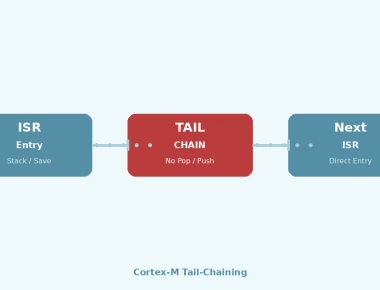
When an ISR completes and another interrupt of sufficient priority is already pending, the NVIC skips the full unstack/stack sequence. Instead of popping 8 registers (R0–R3, R12, LR, PC, xPSR) and pushing them again for the next ISR, it aborts the unstacking, updates the IPSR, and fetches the exception vector for the newly pending interrupt directly into the PC.
// Tail chaining sequence (6 cycles on Cortex-M3/M4 zero wait-state)// vs 12 cycles exit + 12 cycles entry = 24 cycles without optimization// ISR exit with pending interrupt:BX LR // LR contains EXC_RETURN (0xFFFFFFF1 = handler mode/MSP, 0xFFFFFFF9 = thread mode/MSP)// NVIC detects pending interrupt, skips pop/push, jumps to next vector
This optimization is automatic — no software configuration required. It activates whenever a pending interrupt has sufficient priority to be taken (i.e., higher priority than the context being returned to).
If a higher priority interrupt becomes pending during the stacking phase (first 12 cycles of entry), the NVIC continues the stacking process (since the stacked state is identical for all exceptions) but abandons the original vector fetch. It immediately starts fetching the vector for the higher priority ISR. The original interrupt is then tail-chained after the higher priority ISR completes.
Timeline without late arrival:[Stacking 12 cycles] → [ISR Low] → [Unstacking 12 cycles] → [Stacking 12 cycles] → [ISR High]Timeline with late arrival (high priority arrives at cycle 6):[ Stacking 12 cycles total ] → [ISR High] → [Tail chain 6 cycles] → [ISR Low]
If an interrupt arrives during the unstacking phase (ISR exit), the NVIC halts unstacking and immediately begins the new ISR entry. This is the exit-phase counterpart to late arrival.
Cortex-M provides three special-purpose registers for interrupt masking, accessible via MSR/MRS instructions or CMSIS intrinsics.
Single-bit register. When set to 1, masks all configurable-priority exceptions (all IRQs). NMI, HardFault, and Reset remain active.
// CMSIS intrinsics__disable_irq(); // PRIMASK = 1__enable_irq(); // PRIMASK = 0// Assembly equivalent// CPSID i // Disable interrupts (PRIMASK = 1)// CPSIE i // Enable interrupts (PRIMASK = 0)
Use case: Short critical sections where absolutely no preemption is acceptable (e.g., manipulating linked lists shared with ISRs). Blocks all interrupts — use sparingly in RTOS contexts.
Similar to PRIMASK but also masks HardFault. Only NMI remains active. Note: Neither FAULTMASK nor BASEPRI are available on the ARMv6-M architecture (Cortex-M0/M0+).
__disable_fault_irq(); // FAULTMASK = 1__enable_fault_irq(); // FAULTMASK = 0
Use case: Exception handling code that must not be interrupted by any fault except NMI.
8-bit register (implements only the implemented priority bits). Masks all interrupts with priority numerically greater than or equal to BASEPRI value (i.e., lower or equal priority). Interrupts with higher priority (lower numerical value) remain unmasked.
// CMSIS: __set_BASEPRI(priority << (8 - __NVIC_PRIO_BITS))// Example: mask priorities 0x80 and lower (higher numerical = lower priority)__set_BASEPRI(0x80); // Allow priorities < 0x80 (higher urgency)__set_BASEPRI(0); // Clear mask (allow all)
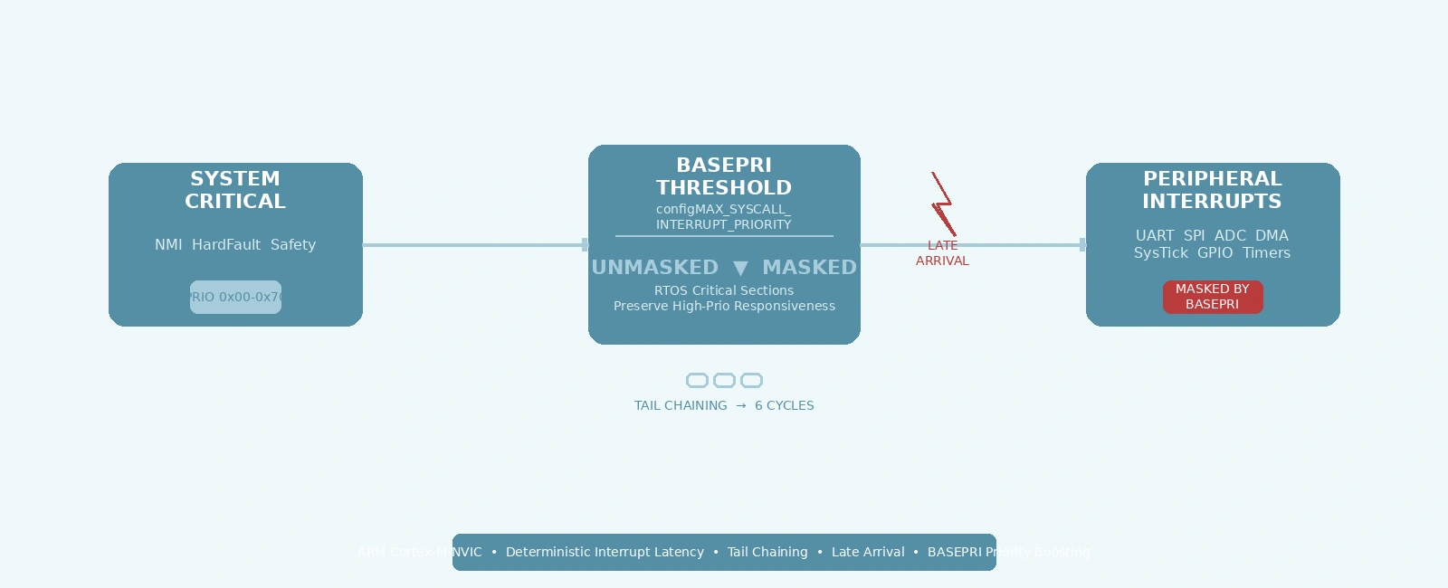
Critical insight: BASEPRI enables selective interrupt masking — the foundation of RTOS critical sections that preserve high-priority interrupt responsiveness.
FreeRTOS and Zephyr use BASEPRI for task-level critical sections (taskENTER_CRITICAL/taskEXIT_CRITICAL). The kernel defines configMAX_SYSCALL_INTERRUPT_PRIORITY (FreeRTOS) or CONFIG_MAX_SYSCALL_INTERRUPT_PRIORITY (Zephyr) — the highest priority level that ISRs can use FreeRTOS/Zephyr API functions.
// FreeRTOS Cortex-M port (simplified masking helpers)#define configMAX_SYSCALL_INTERRUPT_PRIORITY (0x80) // Example: priority 128 (8-bit)// Raise BASEPRI and return the previous mask state (used in ISRs)uint32_t ulPortRaiseBASEPRI(void) {uint32_t ulReturn;uint32_t ulNewBASEPRI = configMAX_SYSCALL_INTERRUPT_PRIORITY;__asm volatile ("mrs %0, basepri\n" // Save current BASEPRI"msr basepri, %1\n" // Set new mask"dsb\n" // Data synchronization barrier (ensure write completes)"isb\n" // Instruction synchronization barrier (flush pipeline): "=r" (ulReturn): "r" (ulNewBASEPRI): "memory");return ulReturn;}// Restore BASEPRI mask to a previously saved statevoid vPortSetBASEPRI(uint32_t ulOriginalBASEPRI) {__asm volatile ("msr basepri, %0\n""dsb\n""isb\n": : "r" (ulOriginalBASEPRI) : "memory");}
Key design: Interrupts above configMAX_SYSCALL_INTERRUPT_PRIORITY (e.g., priority 0x00–0x7F) are never masked by kernel critical sections. These “system-critical” interrupts (e.g., motor control PWM fault, safety watchdog) retain true real-time response.
Priority levels (lower number = higher priority):NMI (fixed -2) --- Never maskable (hardware fixed)HardFault (-1) --- Masked only by FAULTMASK0x00 ------------------+ Highest configurable priority0x10 ------------------+ e.g., Safety watchdog, motor fault0x20 ------------------+ Never masked by BASEPRI0x30 ------------------+ (above configMAX_SYSCALL threshold)0x40 ------------------+ MUST NOT call FreeRTOS API0x50 ------------------+0x60 ------------------+0x70 ------------------++----- configMAX_SYSCALL_INTERRUPT_PRIORITY = 0x800x80 ------------------+ MASKED by BASEPRI in critical sections0x90 ------------------+ CAN call FreeRTOS FromISR APIs0xA0 ------------------+ Typical peripheral ISRs (UART, SPI, timers)0xB0 ------------------+0xC0 ------------------+0xD0 ------------------+0xE0 ------------------+0xF0 ------------------+ Lowest priority (PendSV, SysTick)
During context switching, the kernel must manipulate task stacks and scheduler data structures atomically. FreeRTOS uses priority boosting via BASEPRI in vTaskSwitchContext() (called from PendSV):
// Simplified FreeRTOS context switch (PendSV handler)void PendSV_Handler(void) {// Boost priority to mask all API-callable interrupts__set_BASEPRI(configMAX_SYSCALL_INTERRUPT_PRIORITY);// Save current task context (R4-R11, PSP)// Select next task (scheduler)// Restore next task context// Restore BASEPRI__set_BASEPRI(0);}
This ensures the context switch cannot be preempted by an ISR that might also call the scheduler (e.g., xTaskNotifyFromISR()), which would corrupt kernel state.
// Priority assignment for a typical Cortex-M4 application (e.g., STM32)// Using PRIGROUP = 4 (3-bit group priority, 1-bit subpriority) to allow tie-breaking// Note: For FreeRTOS MAX_SYSCALL_INTERRUPT_PRIORITY, you still need the shifted value#define PRIO_MAX_SYSCALL_SHIFTED 0x80 // configMAX_SYSCALL_INTERRUPT_PRIORITY// Logical Group Priorities (0 to 7)#define GROUP_PRIO_HIGHEST 0 // NMI, HardFault (fixed)#define GROUP_PRIO_SAFETY_WATCHDOG 1 // Never masked (above MAX_SYSCALL)#define GROUP_PRIO_MOTOR_FAULT 2 // Never masked#define GROUP_PRIO_COMM_CRITICAL 3 // CAN bus-off, Ethernet PTP// --- FreeRTOS configMAX_SYSCALL_INTERRUPT_PRIORITY boundary (Group 4) ---#define GROUP_PRIO_HIGH_FREQ_TIMER 4 // e.g., 50kHz control loop#define GROUP_PRIO_UART_DMA 5 // DMA complete callbacks#define GROUP_PRIO_SPI_DMA 5#define GROUP_PRIO_ADC_COMPLETE 5#define GROUP_PRIO_GPIO_BUTTON 6 // Low priority, debounced in task#define GROUP_PRIO_LOWEST 7 // SysTick & PendSV (Must be lowest!)// Configure priority groupingNVIC_SetPriorityGrouping(4);uint32_t prigroup = NVIC_GetPriorityGrouping();// Configure priorities using CMSIS EncodePriorityNVIC_SetPriority(TIM2_IRQn, NVIC_EncodePriority(prigroup, GROUP_PRIO_HIGH_FREQ_TIMER, 0));NVIC_SetPriority(USART1_IRQn, NVIC_EncodePriority(prigroup, GROUP_PRIO_UART_DMA, 0));NVIC_SetPriority(EXTI0_IRQn, NVIC_EncodePriority(prigroup, GROUP_PRIO_GPIO_BUTTON, 0));// Note: FreeRTOS configures SysTick and PendSV automatically in xPortStartScheduler()
Subpriority resolves tie-breaking when multiple interrupts share the same group priority. Use subpriority for:
// Subpriority assignment (lower = higher urgency within the same group)// Using 1-bit subpriority (0 or 1)NVIC_SetPriority(DMA1_Stream0_IRQn, NVIC_EncodePriority(prigroup, GROUP_PRIO_SPI_DMA, 0));NVIC_SetPriority(DMA1_Stream1_IRQn, NVIC_EncodePriority(prigroup, GROUP_PRIO_SPI_DMA, 1));
Use a GPIO toggle + logic analyzer or cycle counter (DWT_CYCCNT) to measure actual latency:
// Enable DWT cycle counterCoreDebug->DEMCR |= CoreDebug_DEMCR_TRCENA_Msk;DWT->CYCCNT = 0;DWT->CTRL |= DWT_CTRL_CYCCNTENA_Msk;// In ISR entryuint32_t cycles = DWT->CYCCNT - g_interrupt_assert_cycle;// GPIO toggle method (external trigger)void EXTI0_IRQHandler(void) {GPIOA->ODR ^= (1 << 5); // Toggle PA5 for logic analyzerEXTI->PR = EXTI_PR_PR0; // Clear pending}
Typical Cortex-M4 latencies (zero wait-state flash):
| Pitfall | Symptom | Fix |
|---|---|---|
| PRIMASK in ISR | Deadlock, missed deadlines | Use BASEPRI in ISRs; never PRIMASK/FAULTMASK |
| Wrong PRIGROUP | Priority inversion, unexpected preemption | Configure once at startup; verify with __NVIC_GetPriorityGrouping() |
| BASEPRI not restored | Interrupts permanently masked | Use __get_BASEPRI()/__set_BASEPRI() pairs; check all exit paths |
| Subpriority ignored | Non-deterministic ISR order | Set explicit subpriorities for same-group interrupts |
| ISR calls blocking API | HardFault, kernel crash | Only use FromISR APIs; check configMAX_SYSCALL_INTERRUPT_PRIORITY |
+==============================================================+| CORTEX-M PRIORITY HIERARCHY || (Lower numerical value = Higher urgency) |+==============================================================+| || PRIORITY LEVEL | MASKING BEHAVIOR || ----------------------------|-------------------------------|| || Reset (-3) ############### Hardware fixed priorities || NMI (-2) # NEVER MASKED # Cannot be disabled || HardFault(-1)############### (Only FAULTMASK masks HF) || || 0x00 - 0x70 ############### User-Configurable Interrupts || # UNMASKED by # Safety watchdog, motor || # BASEPRI in # fault, CAN bus-off, PTP || # critical sect. # MUST NOT call RTOS APIs || ############### (Priority < MAX_SYSCALL) || || 0x80 ======================== configMAX_SYSCALL_INTERRUPT || ^ _PRIORITY threshold || | (BASEPRI set to this value) || | || 0x80 - 0xF0 ============= Maskable by BASEPRI || = Peripheral ISRs = UART, SPI, ADC, Timers, || = (can call RTOS = DMA, GPIO, I2C || = FromISR APIs) = (Priority >= MAX_SYSCALL) || ============= || || 0xFF ~~~~~~~~~~~~~~~~~~~~~~ Thread Mode (Tasks) || ~ LOWEST PRIORITY ~~~ Preempted by ALL interrupts || ~~~~~~~~~~~~~~~~~~~~~~ |+==============================================================+
WITHOUT OPTIMIZATIONS (Naive ISR Entry/Exit):====================================================================ISR Low Priority ISR High Priority+---------------------+ +---------------------+| Stacking (12 cyc) | | Stacking (12 cyc) |+---------------------+ +---------------------+| ISR Body | | ISR Body |+---------------------+ +---------------------+| Unstacking (12 cyc) | | Unstacking (12 cyc) |+---------------------+ +---------------------+Total: ~36 cycles per ISR transitionWITH TAIL CHAINING (Lower-priority interrupt pending at ISR exit):====================================================================ISR High Priority+---------------------+| Stacking (12 cyc) |+---------------------+| ISR Body |+---------------------+| Exit + Tail Chain |---> 6 cycles (vs 24 for full unstack+restack)| (6 cyc) |+---------------------+ISR Low Priority (was pending during High)+---------------------+| (Stacking skipped) |+---------------------+| ISR Body |+---------------------+| Unstacking (12 cyc) |+---------------------+WITH LATE ARRIVAL (High priority arrives during Low stacking):====================================================================Time ---------------------------------------------------------------------------------->[ Stacking 12 cycles total (Shared) ][ISR High][Tail 6cyc][ISR Low][Unstack 12cyc]^ ^ ^ ^ ^| | | | |Cycle 0 Cycle 6 Cycle 12 Cycle x Cycle yLow IRQ High IRQ High ISR Tail chainasserted arrives entry to Low
The Cortex-M NVIC’s hardware optimizations — tail chaining, late arrival, and pop pre-emption — dramatically reduce interrupt overhead without software intervention. The key to leveraging these in production firmware is proper priority configuration:
NVIC_SetPriorityGrouping() to define the split between group and subpriority)configMAX_SYSCALL_INTERRUPT_PRIORITY for safety-critical interrupts that must never be maskedThese practices ensure your interrupt subsystem remains deterministic, responsive, and debuggable — even under heavy interrupt load.
portable/GCC/ARM_CM3/portmacro.h and portable/GCC/ARM_CM4F/portmacro.hQuick Links
Legal Stuff