


Boot Sequence and Reset Handling in Embedded Systems
June 30, 2026
3 min
When firmware written for an STM32 refuses to run on an nRF52 without rewriting every peripheral driver, the absence of a Hardware Abstraction Layer (HAL) is almost always the culprit. A well-designed HAL is the single most impactful architectural decision an embedded team can make — it decouples application logic from silicon specifics, enabling code reuse across product lines, simplifying unit testing, and dramatically reducing porting effort when silicon vendors change.
Despite its importance, HAL design is often approached ad hoc, resulting in leaky abstractions that tie application code directly to register-level details. This article explores the core principles, patterns, and practical techniques for building a robust HAL that stands the test of time.
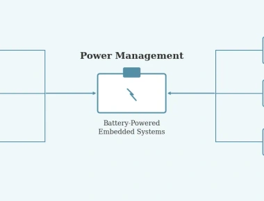
Consider a typical embedded project: the application reads sensor data over SPI, processes it, and transmits results over UART. Without a HAL, the application calls vendor-specific SPI and UART functions directly. When the MCU changes — perhaps due to supply chain constraints or a product upgrade — every peripheral call must be rewritten.
A HAL solves this by defining a stable interface between application code and hardware. The application calls spi_transfer() and uart_send(), while the HAL implementation underneath maps those calls to the actual hardware registers of whichever MCU is in use. Swap the MCU, swap the HAL implementation, and the application code remains untouched.
Beyond portability, a HAL enables hardware-independent testing. By providing a mock implementation of the HAL interface, developers can run and test application logic on a host PC without any target hardware.
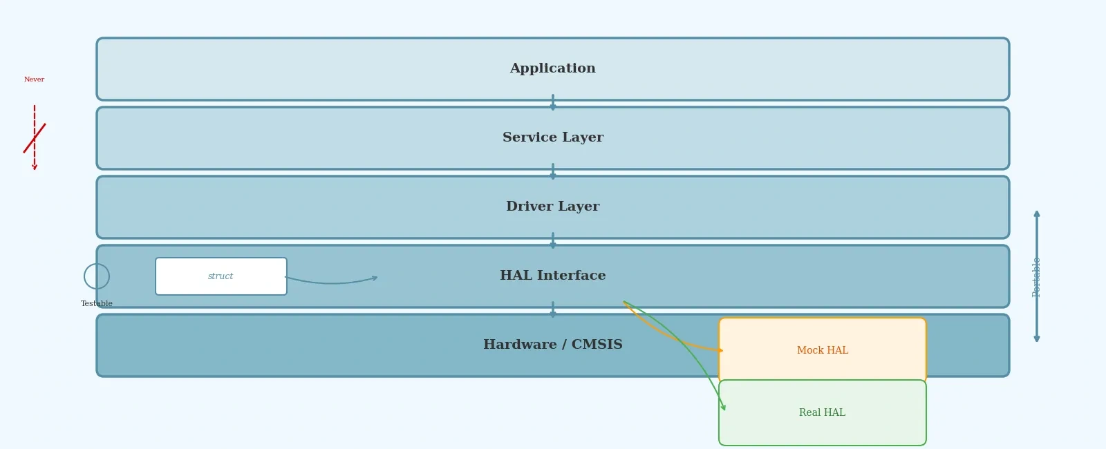
The most important architectural rule in embedded firmware is directional dependency. Upper layers call lower layers, never the reverse. A typical stack looks like this:
No layer should reach upward or skip a layer. This rule makes firmware testable (mock the layer below in unit tests), portable (swap the HAL to retarget), and maintainable (change application logic without touching drivers).
Violating directional dependency is how firmware accumulates technical debt that eventually makes a codebase unmaintainable.
A good HAL interface should be human-readable, abstracted, portable, and extensible. For each peripheral, aim for a small set of generic functions — typically fewer than a dozen. Expose only what the caller needs; hide everything else.
In C, the most effective HAL pattern uses function pointer structs — the equivalent of virtual function tables in C++. Each platform provides its own concrete implementation of the struct. Layers above hold a pointer to the interface and call through it, never knowing which platform they are running on.
/* hal_gpio.h — Platform-agnostic GPIO interface */typedef struct {void (*init)(uint8_t pin, uint8_t mode);void (*write)(uint8_t pin, uint8_t value);uint8_t (*read)(uint8_t pin);void (*toggle)(uint8_t pin);} hal_gpio_interface_t;/* Application code receives a pointer to the interface */void app_set_led(const hal_gpio_interface_t *gpio, uint8_t pin) {gpio->write(pin, 1);}
This pattern is directly inspired by CMSIS-Driver, where ARM_DRIVER_USART and similar structs define standardized peripheral interfaces. The struct can be allocated statically at link time, const-qualified for ROM placement, and injected via pointer into the layer above — zero heap usage, zero runtime overhead.
For teams using C++, two main approaches exist. Dynamic polymorphism uses inheritance and virtual methods:
class GpioBase {public:virtual void write(bool value) = 0;virtual bool read() = 0;virtual ~GpioBase() = default;};class Stm32Gpio : public GpioBase {void write(bool value) override { /* STM32 register access */ }bool read() override { /* STM32 register access */ }};
This is intuitive and gives clear compile-time errors when methods are missing, but introduces vtable lookup overhead. For most embedded applications this overhead is negligible, but on deeply constrained MCUs it can matter.
Static polymorphism via templates and CRTP eliminates runtime overhead entirely:
template<typename Derived>class GpioBase {public:void write(bool value) {static_cast<Derived*>(this)->write_impl(value);}};class Stm32Gpio : public GpioBase<Stm32Gpio> {public:void write_impl(bool value) { /* STM32 register access */ }};
Since all types are known at compile time in embedded systems, losing runtime polymorphism is rarely a concern. The trade-off is slightly more complex template code and less obvious compiler errors.
Creating a solid HAL is iterative. A proven seven-step process works for each peripheral:
Start with GPIO and UART — the most commonly used peripherals — then expand to SPI, I2C, ADC, timers, and DMA as needed.
Leaky abstractions occur when HAL functions expose hardware-specific details that callers start depending on. If your SPI transfer function requires the caller to manually manage a chip select pin, the abstraction is leaking.
Over-abstracting is the opposite trap. A HAL that tries to support every possible peripheral mode and configuration becomes as complex as the hardware itself. Start simple and add features only when needed.
Ignoring the build system can undermine an otherwise good HAL design. Use the build system to select the correct HAL implementation at compile time, not runtime conditionals scattered through the code.
A well-designed HAL is the foundation of maintainable, portable, and testable embedded firmware. Key takeaways:
Investing in a proper HAL upfront pays dividends across every future project that shares the codebase.
Quick Links
Legal Stuff