


FreeRTOS Heap Implementations Compared: Heap_1 to Heap_5
July 14, 2026
5 min
Battery-powered embedded devices live and die by their power budget. Every microamp matters when a coin cell must last five years. While hardware designers have long exploited microcontroller sleep modes, integrating those modes with a real-time operating system requires deliberate architectural choices. This article explores practical low-power design patterns for RTOS-based systems.
In a typical RTOS configuration, a hardware timer generates a periodic tick interrupt — usually every 1 ms — to drive the scheduler. Even when no application tasks are ready to run, the tick interrupt fires, waking the CPU from any low-power state just to increment the tick counter and return to idle. At 1 kHz, that is 86.4 million unnecessary wake-ups per day.
The naive approach is to place the MCU into a light sleep mode inside the idle task hook (vApplicationIdleHook). The CPU halts, the tick interrupt wakes it, the kernel runs the scheduler, finds nothing to do, and goes back to sleep. The power savings are real but limited: the energy spent entering and exiting sleep every millisecond can easily outweigh the savings, especially if the sleep mode has a non-trivial wake-up latency.
FreeRTOS and most modern RTOS implementations solve this with tickless idle mode. The idea is straightforward: when the kernel determines that no tasks are ready to execute for a meaningful duration, it stops the tick interrupt entirely, calculates when the next wake-up is needed, and programs a secondary timer (or RTC) to fire at that future point. The MCU can then enter a deep sleep state for seconds or even minutes.
Enabling tickless mode in FreeRTOS requires a single configuration change in FreeRTOSConfig.h:
#define configUSE_TICKLESS_IDLE 1#define configEXPECTED_IDLE_TIME_BEFORE_SLEEP 5
Setting configUSE_TICKLESS_IDLE to 1 enables the built-in tickless implementation provided by the port layer (all ARM Cortex-M ports include one). Setting it to 2 lets you provide your own implementation of portSUPPRESS_TICKS_AND_SLEEP(). The configEXPECTED_IDLE_TIME_BEFORE_SLEEP threshold prevents the kernel from entering tickless mode when the idle period is too short to justify the overhead of stopping and restarting the tick.
When tickless mode activates, the kernel suspends the scheduler and calls portSUPPRESS_TICKS_AND_SLEEP(xExpectedIdleTime). The parameter xExpectedIdleTime tells the port layer how many tick periods the MCU can safely remain asleep. A typical port layer implementation then:
vTaskStepTick()After the macro returns, the kernel resumes the scheduler.
The tick count correction is critical. If the MCU wakes early due to an external interrupt (not the scheduled timer), the kernel must account for the partial sleep to maintain accurate timekeeping.
Not all sleep modes are equal. ARM Cortex-M processors typically offer three levels:
| Mode | CPU Clock | Peripherals | Wake Sources | Typical Current |
|---|---|---|---|---|
| Sleep | Stopped | Running | Any interrupt | ~1-5 mA |
| Deep Sleep | Stopped | Configurable | Selected interrupts | ~10-100 uA |
| Power-Down | Off | Off | Reset, RTC | ~1-5 uA |
The deeper the sleep, the fewer peripherals remain active and the longer the wake-up latency. A key design decision is matching the sleep mode to the expected idle duration. For short idle periods (a few milliseconds), deep sleep may not be worth the wake-up cost. For long idle periods (seconds or more), power-down mode can reduce current from milliamps to microamps.
+----------+ --- idle --> +--------------+ --- deep ---> +----------------+| Active | --- idle --> | Sleep Mode | --- deep ---> | Deep Sleep || Task |<-- interrupt | (light) |<-- interrupt--| (power-down) |+----------+ --- idle --> +--------------+ --- deep ---> +----------------+| || timer / | RTC /| interrupt | interruptv v+-------------------------------------------------------------------------+| Wake-Up ISR || measure elapsed sleep, advance tick count |+-------------------------------------------------------------------------+
The eTaskConfirmSleepModeStatus() API helps here. It returns one of three values:
eAbortSleep — a task became ready while we were preparing; abort the sleepeStandardSleep — tasks are blocked with finite timeouts; sleep for at most xExpectedIdleTimeeNoTasksWaitingTimeout — all tasks are suspended or blocked with infinite timeout; sleep indefinitely (wake only by external interrupt)This lets the custom portSUPPRESS_TICKS_AND_SLEEP() implementation confirm whether it is still safe to proceed with the sleep mode, and whether it should sleep indefinitely.
FreeRTOS provides two macros for application-specific power management around sleep transitions. configPRE_SLEEP_PROCESSING and configPOST_SLEEP_PROCESSING map to user-defined functions called before and after sleep. Common pre-sleep actions include gating peripheral clocks, reducing system frequency, and disabling debug UARTs. The post-sleep counterpart restores everything. These hooks are the ideal place to implement platform-specific power optimizations without modifying the kernel.
A practical pattern for peripheral power management is to track usage with reference counters. Each peripheral’s driver increments a counter on acquire and decrements on release. When the counter reaches zero, the peripheral clock is gated. This ensures that peripherals like SPI, I2C, and ADC draw zero dynamic power when no task is using them. Because these functions can be called concurrently from different tasks, the reference counter must be protected by a critical section to prevent race conditions.
typedef struct {volatile uint8_t ref_count;uint32_t clock_bit;} peripheral_power_t;void peripheral_acquire(peripheral_power_t *p){taskENTER_CRITICAL();if (p->ref_count == 0) {/* Enable peripheral clock */PMC->PMC_PCER0 = p->clock_bit;}p->ref_count++;taskEXIT_CRITICAL();}void peripheral_release(peripheral_power_t *p){taskENTER_CRITICAL();if (p->ref_count > 0) {p->ref_count--;if (p->ref_count == 0) {/* Disable peripheral clock */PMC->PMC_PCDR0 = p->clock_bit;}}taskEXIT_CRITICAL();}
This pattern works well with tickless idle: when all tasks are blocked and all peripherals are released, the kernel can confidently enter the deepest sleep mode.
In deep sleep modes, the processor clock — and therefore SysTick — may stop. A secondary timer powered by an always-on clock domain (such as an RTC at 32.768 kHz) must serve as the wake-up source. The trade-off is reduced time granularity: an RTC tick is ~30.5 us compared to SysTick’s nanosecond resolution. For battery-powered applications, this is an excellent trade-off.
At the application level, tasks should be designed to maximize idle time. Instead of polling with short delays, tasks should block on RTOS primitives (queues, semaphores, event flags) and let the kernel enter sleep when nothing needs attention.
/* BAD: Polling wastes power */void sensor_task_bad(void *param){while (1) {if (sensor_data_ready()) {process_data();}vTaskDelay(pdMS_TO_TICKS(10));}}/* GOOD: Blocking maximizes sleep opportunities */void sensor_task_good(void *param){while (1) {/* Block indefinitely until ISR gives semaphore */if (xSemaphoreTake(sensor_sem, portMAX_DELAY) == pdTRUE) {process_data();}}}
The second version lets the kernel enter tickless idle for the entire duration the sensor is not ready, potentially saving milliamps of current.
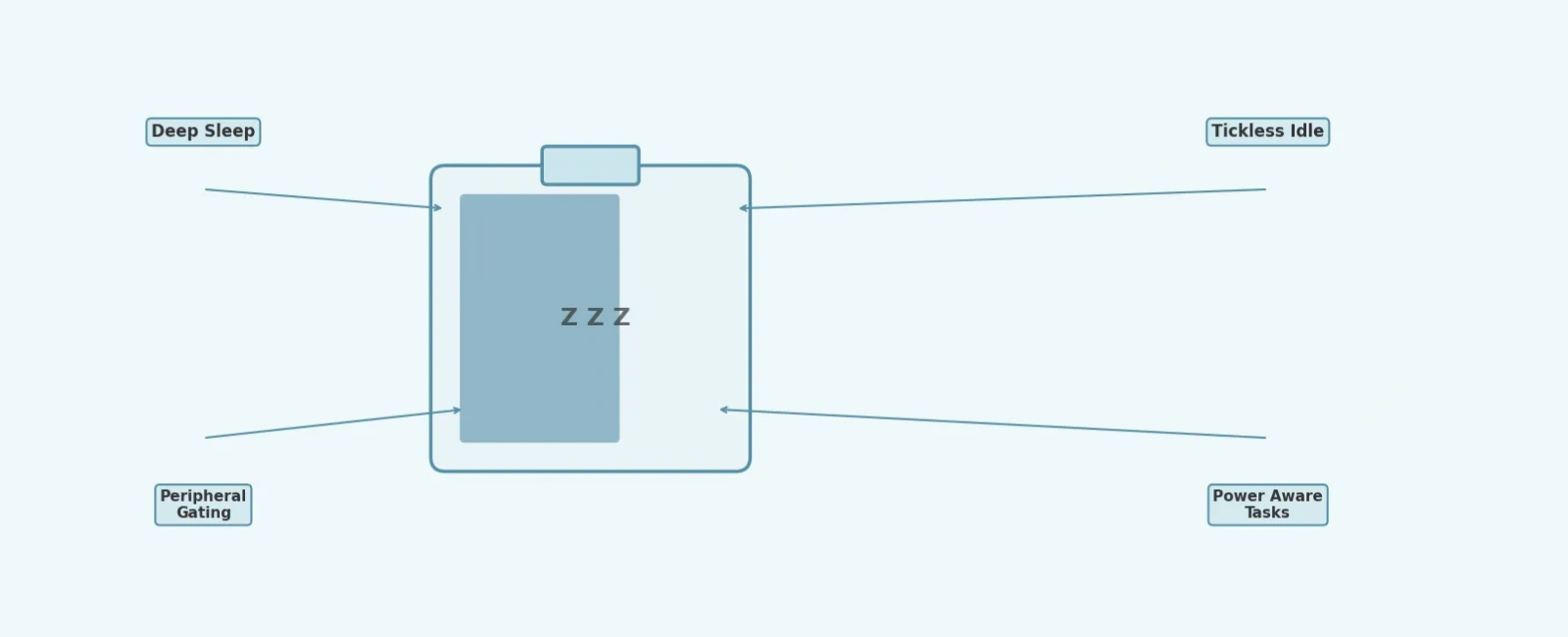
Low-power design in RTOS-based systems is a layered effort. Tickless idle mode eliminates the wasteful periodic tick during idle periods. Pre- and post-sleep hooks let you gate clocks and reduce voltages. Peripheral reference counting ensures unused peripherals draw no power. And power-aware task design — blocking instead of polling — maximizes sleep time. Together, these patterns can reduce average current consumption by an order of magnitude, turning a device that lasts days into one that lasts years.
Quick Links
Legal Stuff