


Memory-Mapped IO and Peripheral Register Access in Embedded C
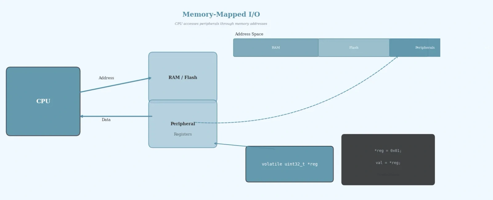
Table Of Contents
Introduction
Every microcontroller communicates with its peripherals — GPIOs, UARTs, timers, ADCs — through a set of hardware registers. In most modern embedded architectures, including ARM Cortex-M, these registers are mapped directly into the processor’s memory address space. This technique, known as memory-mapped I/O (MMIO), allows the CPU to read and write peripheral registers using ordinary memory access instructions, without needing special I/O opcodes.
Understanding memory-mapped I/O is fundamental for any embedded engineer. Whether you are toggling an LED, configuring a UART baud rate, or setting up a DMA transfer, you are ultimately reading and writing to memory-mapped registers. This article explores how MMIO works, why the volatile keyword is essential, and how to write clean, reliable register access code in embedded C.
How Memory-Mapped I/O Works
In a memory-mapped I/O system, the address space of the processor is divided into regions. Some addresses correspond to actual RAM or flash memory, while others are mapped to peripheral registers. When the CPU writes to a peripheral register address, the memory controller routes the write to the corresponding hardware block instead of to physical memory.
For example, on an STM32F4 microcontroller, the GPIOA peripheral might start at base address 0x40020000. The GPIO Mode Register (MODER) is at offset 0x00, the Output Data Register (ODR) at offset 0x14, and the Input Data Register (IDR) at offset 0x10. Each register is 32 bits wide, and the addresses are consecutive in the peripheral memory region.
This means that configuring pin 5 of GPIOA as an output involves writing to the address 0x40020000 + 0x00, and toggling that pin means writing to 0x40020000 + 0x14. The processor treats these as memory locations, but the hardware interprets them as peripheral control signals.
The Volatile Keyword: Why It Matters
One of the most critical aspects of memory-mapped I/O in C is the volatile keyword. Hardware registers can change value at any time — outside the control of your program. A status bit might flip when a UART receives a byte, or a timer counter might increment with every clock cycle.
Without volatile, the compiler may optimize away what it considers redundant reads or writes. For example, if your code reads a status register twice in succession, the compiler might cache the first result and skip the second read. With hardware registers, this is incorrect — the value may have changed between reads.
// Without volatile — compiler may optimize away repeated readsuint32_t status = *(uint32_t*)0x40020010; // First read// ... some code ...uint32_t status2 = *(uint32_t*)0x40020010; // Compiler might reuse 'status'// With volatile — every access goes to the actual registervolatile uint32_t *status_reg = (volatile uint32_t*)0x40020010;uint32_t status = *status_reg; // Always reads from hardwareuint32_t status2 = *status_reg; // Always reads from hardware again
The volatile qualifier tells the compiler that the value at this address can change unexpectedly, forcing it to generate a memory access for every read and write.
Defining Register Access Macros
The most common pattern for accessing memory-mapped registers in embedded C is through macros or pointer definitions. Here is a practical example for an STM32 GPIO peripheral:
// Base address for GPIOA peripheral#define GPIOA_BASE 0x40020000U// Register offsets from base#define GPIOA_MODER (*(volatile uint32_t *)(GPIOA_BASE + 0x00U))#define GPIOA_OTYPER (*(volatile uint32_t *)(GPIOA_BASE + 0x04U))#define GPIOA_OSPEEDR (*(volatile uint32_t *)(GPIOA_BASE + 0x08U))#define GPIOA_PUPDR (*(volatile uint32_t *)(GPIOA_BASE + 0x0CU))#define GPIOA_IDR (*(volatile uint32_t *)(GPIOA_BASE + 0x10U))#define GPIOA_ODR (*(volatile uint32_t *)(GPIOA_BASE + 0x14U))#define GPIOA_BSRR (*(volatile uint32_t *)(GPIOA_BASE + 0x18U))// Bit definitions#define GPIO_PIN5 (1U << 5)// Configure pin 5 as outputvoid gpio_init(void) {// Set MODER bits for pin 5 to 01 (general purpose output)GPIOA_MODER &= ~(3U << (5 * 2)); // Clear mode bitsGPIOA_MODER |= (1U << (5 * 2)); // Set as output}// Toggle pin 5void gpio_toggle(void) {GPIOA_ODR ^= GPIO_PIN5;}
Each macro casts the integer address to a volatile uint32_t pointer and dereferences it. This gives you a readable name that behaves like a variable, while ensuring every access goes to the actual hardware register.
Read-Modify-Write Operations
Many register operations require a read-modify-write pattern: you read the current value, modify specific bits, and write the result back. This is essential when you want to change one field in a register without affecting others.
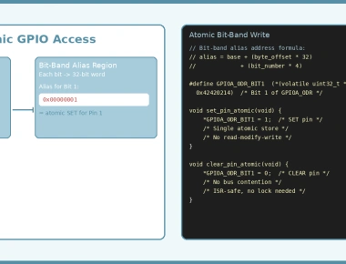
// Set pin 5 to high-speed output without affecting other pinsGPIOA_OSPEEDR |= (3U << (5 * 2)); // Set both speed bits for pin 5// Clear pin 5 output type to push-pull without affecting othersGPIOA_OTYPER &= ~(1U << 5); // Clear bit 5 for push-pull// Atomic set/reset using BSRR (bit set/reset register)GPIOA_BSRR = (1U << 5); // Set pin 5 highGPIOA_BSRR = (1U << (5 + 16)); // Set pin 5 low (reset via upper 16 bits)
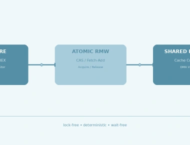
The BSRR register is particularly elegant — it allows atomic set and reset operations without read-modify-write, which is critical in interrupt-driven code where another context might be modifying the same register.
Struct-Based Register Mapping
For more complex peripherals, you can define a struct that mirrors the register layout. This approach is cleaner and is used in many microcontroller header files:
typedef struct {volatile uint32_t MODER; // Mode register (offset 0x00)volatile uint32_t OTYPER; // Output type register (offset 0x04)volatile uint32_t OSPEEDR; // Output speed register (offset 0x08)volatile uint32_t PUPDR; // Pull-up/pull-down (offset 0x0C)volatile uint32_t IDR; // Input data register (offset 0x10)volatile uint32_t ODR; // Output data register (offset 0x14)volatile uint32_t BSRR; // Bit set/reset register (offset 0x18)volatile uint32_t LCKR; // Configuration lock (offset 0x1C)} GPIO_TypeDef;#define GPIOA ((GPIO_TypeDef *)0x40020000U)// UsageGPIOA->ODR ^= GPIO_PIN5; // Toggle pin 5GPIOA->MODER &= ~(3U << (5 * 2)); // Clear mode bits for pin 5GPIOA->MODER |= (1U << (5 * 2)); // Set pin 5 as output
This struct-based approach is how CMSIS and vendor headers (like STM32 HAL) organize peripheral registers. Each member’s position in the struct corresponds to its offset from the base address.
Common Pitfalls
Forgetting volatile: The most common mistake. Without volatile, the compiler may optimize away hardware register accesses, leading to code that works in debug builds but fails with optimizations enabled.
Incorrect bit widths: Using uint8_t pointers for 32-bit registers can cause the compiler to generate byte-level accesses that the hardware does not support. Always match the pointer type to the register width.
Race conditions in read-modify-write: When modifying a single bit in a shared register from both main code and an interrupt, use atomic operations (like BSRR) or disable interrupts during the read-modify-write sequence.
Unaligned accesses: Some architectures require aligned memory accesses. Casting to the wrong type or using incorrect addresses can trigger hard faults.
Summary
Memory-mapped I/O is the backbone of embedded systems programming. By mapping hardware registers into the address space, microcontrollers allow direct peripheral control through simple pointer operations in C. The key takeaways are:
- Always use
volatilewhen accessing hardware registers to prevent compiler optimizations - Use macros or struct-based mappings for clean, maintainable register access code
- Prefer atomic bit-set/reset registers (like BSRR) over read-modify-write when available
- Match pointer types to register widths to ensure correct bus transactions
- Be mindful of race conditions when accessing shared registers from multiple contexts
Mastering these concepts will make you a more effective embedded engineer and prepare you for the low-level challenges that come with bare-metal firmware development.
Frequently Asked Questions
How do you access a hardware register in C?
Cast a constant physical memory address to a volatile pointer of appropriate width, and then dereference it. For example: `*(volatile uint32_t *)0x40021000 = 0x01;` sets register value.
Why is the `volatile` keyword mandatory for hardware registers?
Without `volatile`, the compiler's optimizer assumes the register behaves like standard RAM and may optimize away repeated writes or reads. It tells the compiler that the memory location can change asynchronously.
What are the common ways to structure register maps in drivers?
Developers use C structures where the members represent contiguous registers. This matches the hardware layout perfectly and makes it easy to address offsets, like `GPIOA->ODR`.
Previous Article
Static vs Dynamic Memory Allocation in Embedded SystemsNext Article
Memory Protection Unit in Embedded SystemsRelated Posts

Linker Scripts and Memory Layout in Embedded C: A Practical Guide
July 02, 2026
2 min
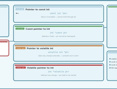
Understanding const and volatile Pointer Types in Embedded C
June 29, 2026
3 min
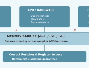
Volatile vs Memory Barriers — When Volatile Isn't Enough
June 20, 2026
5 min
Bit-Banding in Embedded C — Atomic GPIO Manipulation Without Locks
June 19, 2026
3 min
DMA Programming in Embedded C for High-Throughput Data Transfer
June 12, 2026
3 min
Quick Links
Legal Stuff