


Clock Tree and PLL Configuration in Embedded Systems
June 26, 2026
6 min
When you flip the power switch on a microcontroller, a carefully choreographed sequence of hardware and firmware handshakes unfolds before the first line of your main() ever executes. Understanding the boot sequence and reset handling is essential for every embedded developer, because the decisions made in the first few milliseconds determine whether your system starts reliably or silently fails.
Every reset begins with the processor looking up its vector table — an array of function pointers stored at a well-defined memory address (typically 0x00000000 on ARM Cortex-M devices). The first entry is the initial stack pointer value; the second is the reset handler. The hardware automatically loads the stack pointer, then begins executing the reset handler.
/* Simplified startup assembly for ARM Cortex-M */.section .isr_vector.word _estack /* Initial Stack Pointer */.word Reset_Handler /* Reset vector */.word NMI_Handler /* NMI */.word HardFault_Handler/* Hard Fault */
The vector table is the firmware’s root of trust. If it is misaligned, points to the wrong flash bank, or gets corrupted by a faulty bootloader update, the chip will not boot.
The reset handler (often called Reset_Handler) performs the bridge between bare-metal hardware and the C runtime environment. Its responsibilities are non-negotiable:
+--------------------------------------------------+| POWER ON / RESET |+------------------------+-------------------------+|v+------------------------+-------------------------+| Load SP & PC from Vector Table |+------------------------+-------------------------+|v+------------------------+-------------------------+| Reset_Handler (startup.s) || - Set system clock (PLL, HSI/HSE) || - Copy .data: flash -> RAM || - Zero .bss: RAM || - Call SystemInit() |+------------------------+-------------------------+|v+------------------------+-------------------------+| __libc_init_array (C++ constructors) |+------------------------+-------------------------+|v+------------------------+-------------------------+| main() |+------------------------+-------------------------+
A minimal Reset_Handler in assembly looks like this:
void Reset_Handler(void) {/* Copy .data section from Flash to RAM */uint32_t *src = &_sidata;uint32_t *dst = &_sdata;while (dst < &_edata)*dst++ = *src++;/* Zero-fill .bss section */dst = &_sbss;while (dst < &_ebss)*dst++ = 0;/* Call system clock configuration */SystemInit();/* Enter main */main();/* main() should never return */while (1) { }}
The symbols _sdata, _edata, _sidata, _sbss, and _ebss are defined by the linker script, establishing the exact memory boundaries the startup code operates on.
Not all resets are equal. Understanding the reset source helps diagnose faults and design robust recovery.
| Reset Source | Trigger | Recovery Notes |
|---|---|---|
| Power-On Reset (POR) | VDD rising edge | Full initialization required |
| External Reset (nRST pin) | Pin asserted low | GPIO state may be保留 |
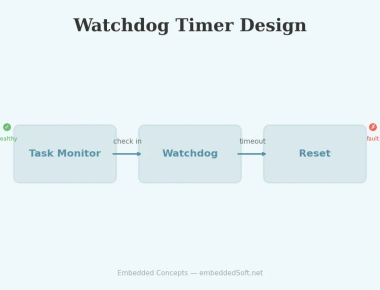
| Watchdog Reset | WDT timeout | Indicates software failure |
| Brown-Out Reset (BOR) | VDD below threshold | Voltage transient occurred |
| Software Reset (SYSRESETREQ) | NVIC application interrupt | Graceful shutdown possible |
Most MCUs expose a Reset Status Register that firmware can read on boot to determine why the previous run ended. This is invaluable for field diagnostics:
void check_reset_cause(void) {uint32_t reset_flags = RCC->CSR;if (reset_flags & RCC_CSR_PORRSTF) {/* Power-on: device was off */}if (reset_flags & RCC_CSR_IWDGRSTF) {/* Independent watchdog timeout */}if (reset_flags & RCC_CSR_SFTRSTF) {/* Software-initiated reset */}/* Clear flags for next boot */RCC->CSR |= RCC_CSR_RMVF;}
The linker script (.ld file) is where the physical memory layout of the target is described. It tells the linker where Flash and RAM begin, how large they are, and where each section goes.
/* STM32F407 memory layout */MEMORY{FLASH (rx) : ORIGIN = 0x08000000, LENGTH = 1024KRAM (rwx) : ORIGIN = 0x20000000, LENGTH = 128K}/* Define symbols used by startup code */_sidemandedata = LOADADDR(.data);_sdata = ADDR(.data);_edata = _sdata + SIZEOF(.data);
Without a correct linker script, the startup code has no way to know where .data lives in flash versus RAM. Misconfigured memory sizes lead to section overlap, silent corruption, or linker errors.
When an application intentionally triggers a software reset, the cause lives only in RAM until the new boot runs. A robust pattern is to store the reason in a backup register or no-init RAM section that survives soft reset:
/* Place in a no-init section that startup does not zero */__attribute__((section(".noinit"))) uint32_t reset_reason;void request_system_reset(uint32_t reason) {reset_reason = reason;NVIC_SystemReset();}void main(void) {if (reset_reason == REASON_FIRMWARE_UPDATE) {/* Jump to bootloader instead of normal app */enter_bootloader();}}
Many production systems need a way to enter the system bootloader after reset — to accept new firmware over UART, USB, or CAN. This is typically done by checking a GPIO pin or a flag in backup RAM before the application initializes peripherals.
void check_bootloader_entry(void) {/* Backup register set by app before requesting reset */if (RTC->BKP0R == BOOTLOADER_MAGIC) {RTC->BKP0R = 0;/* Jump to system bootloader at 0x1FFF0000 */((void (*)(void))(*(__IO uint32_t *)0x1FFF0004))();}}
The boot sequence is far more than a curiosity of microcontroller internals — it is the foundation of system reliability. Key takeaways:
.data, .bss, and the system clock.Mastering these concepts ensures your firmware boots predictably, recovers gracefully from faults, and supports field update workflows.
Quick Links
Legal Stuff