


I2C Protocol Deep Dive for Embedded Systems
June 15, 2026
5 min
Every digital system beats to the rhythm of a clock. In embedded microcontrollers, that rhythm isn’t a single metronome — it’s an entire orchestra of clock sources, multipliers, dividers, and gates that must be carefully orchestrated. Understanding the clock tree is fundamental to building reliable embedded systems, yet it’s one of the most overlooked topics in embedded development.
A simple microcontroller might need to run its CPU at 72 MHz, communicate over USB at 48 MHz, drive timers at a precise rate, and keep an accurate RTC running from a 32.768 kHz crystal — all simultaneously. No single oscillator can satisfy all these requirements efficiently.
The clock tree solves this by providing multiple clock sources and routing them through multipliers (PLLs) and dividers (prescalers) to different clock domains. Each domain can operate at its own optimal frequency, conserving power while meeting timing specifications.
A typical ARM Cortex-M clock tree has these primary components:
+---------------------------+| External Sources || HSE (8 MHz Crystal) || HSI (8 MHz Internal RC) || LSE (32.768 kHz Crystal) || LSI (40 kHz Internal RC) |+---------------------------+|v+---------------------------+| PLL (×9) || 8 MHz × 9 = 72 MHz |+---------------------------+| |v v+----------+ +---------------+| SYSCLK | | USB Prescaler || 72 MHz | | ÷1.5 = 48 MHz |+----------+ +---------------+|v+---------------------------+| Prescalers || AHB (/1) -> 72 MHz || APB1 (/2) -> 36 MHz || APB2 (/1) -> 72 MHz |+---------------------------+
The SYSCLK feeds the CPU core and AHB bus, while the APB prescalers create slower clocks for peripherals that don’t need full speed. This hierarchical structure means a single register write to the PLL configuration can change the operating frequency of the entire system.
A Phase-Locked Loop takes a reference frequency and multiplies it to a higher output frequency. The basic formula for modern Cortex-M devices often looks like this:
F_vco = F_ref × (N / M)F_out = F_vco / P
Where F_ref is the input frequency (typically an external crystal), N is the multiplication factor, and M is the division factor applied to the input. Most microcontrollers constrain N and M to specific ranges to keep the PLL’s internal VCO (Voltage Controlled Oscillator) operating within its valid frequency band. The post-divider P (or sometimes Q/R) steps down the VCO frequency to the final output.
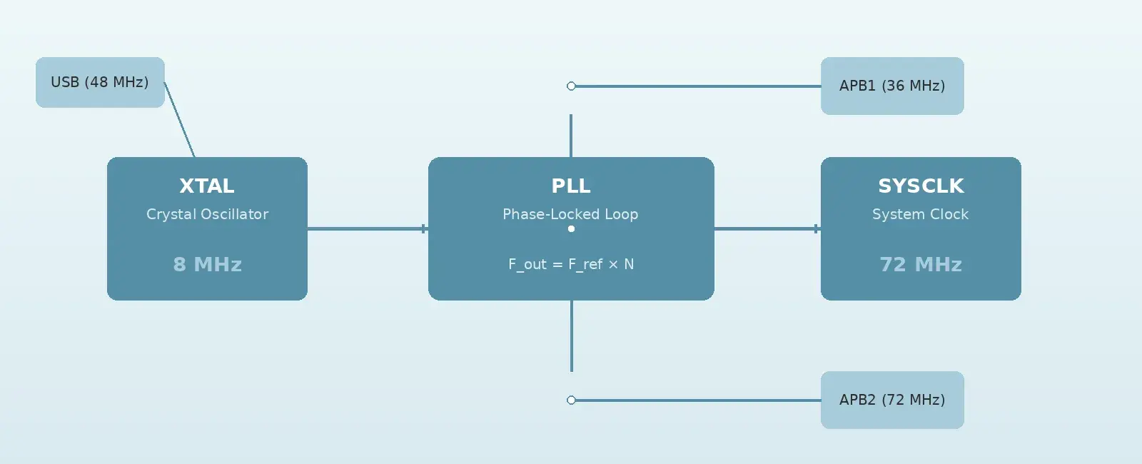
For example, on the STM32F103 (which uses a simpler PLL without a P divider), a common configuration uses an 8 MHz HSE crystal with a pre-divider M=1 and multiplier N=9, producing 72 MHz — the maximum CPU frequency for that family.
+----------+ +-------+ +-------+| HSE | --> | ÷ M | --> | VCO || 8 MHz | | ÷ 1 | | in |+----------+ +-------+ +-------+|+-----+-----+| × N (×9) |+-----+-----+|v+----------+| F_out || 72 MHz |+----------+
The PLL must achieve lock before the system switches to it as its clock source. This lock time is typically in the range of tens to hundreds of microseconds — a critical detail during startup code development.
Modern microcontrollers define several clock domains, each serving different subsystems:
SYSCLK (System Clock): Drives the CPU core, DMA controllers, and memory interfaces. This is the fastest clock domain and directly determines instruction execution speed.
AHB Clock: Derived from SYSCLK, optionally divided. Feeds the system bus, memory, and DMA. Most configurable as a simple integer divider from SYSCLK.
APB1 (Advanced Peripheral Bus 1): Typically limited to half the CPU frequency. Feeds lower-speed peripherals like UART2-5, I2C, timers, and the independent watchdog.
APB2 (Advanced Peripheral Bus 2): Can run at full CPU frequency. Feeds high-speed peripherals like SPI1, USART1, GPIO ports, and the advanced timers.
RTC Clock: Operated from a separate 32.768 kHz crystal (LSE) or internal LSI oscillator. This domain remains active even during sleep modes and system resets.
The critical insight is that peripheral register access timing depends on the APB clock, not the CPU clock. If APB1 is prescaled to 36 MHz while the CPU runs at 72 MHz, an APB transaction requires at least two APB clock cycles. Because the APB is running at half the CPU speed, the bus bridge will stall the CPU for at least four CPU cycles while waiting for the peripheral read/write to complete. In hard real-time systems, this bus stalling must be accounted for in execution time analysis. (Note: This is why high-speed peripherals like GPIOs are placed on faster buses, such as APB2 or AHB1).
Robust embedded systems need to handle clock source failures. Most microcontrollers include a Clock Security System (CSS) that:
This is highly important in safety-critical applications to prevent a total hard lockup if a crystal trace cracks. However, engineers must remember the CSS Aftermath: when the CSS falls back to the internal RC oscillator (e.g., 8 MHz HSI), the PLL is typically bypassed or lost lock. The system clock instantly drops from 72 MHz down to 8 MHz. While the CPU continues executing, all time-dependent peripherals (UART, CAN, Timers) will immediately operate at incorrect baud/tick rates. The NMI handler must be designed to quickly halt actuators, close communication channels, and transition the system to a safe state.
Configuring the clock tree typically follows this sequence during system initialization:
/* Simplified STM32 HAL clock configuration for 72 MHz */void SystemClock_Config(void) {RCC_OscInitTypeDef osc = {0};RCC_ClkInitTypeDef clk = {0};/* HSE + PLL -> 72 MHz */osc.OscillatorType = RCC_OSCILLATORTYPE_HSE;osc.HSEState = RCC_HSE_ON;osc.PLL.PLLState = RCC_PLL_ON;osc.PLL.PLLSource = RCC_PLLSOURCE_HSE;osc.PLL.PLLMUL = RCC_PLL_MUL_9; /* 8 MHz × 9 = 72 MHz */HAL_RCC_OscConfig(&osc);/* Configure bus prescalers */clk.ClockType = RCC_CLOCKTYPE_HCLK | RCC_CLOCKTYPE_SYSCLK| RCC_CLOCKTYPE_PCLK1 | RCC_CLOCKTYPE_PCLK2;clk.SYSCLKSource = RCC_SYSCLKSOURCE_PLLCLK;clk.AHBCLKDivider = RCC_SYSCLK_DIV1; /* 72 MHz */clk.APB1CLKDivider = RCC_HCLK_DIV2; /* 36 MHz */clk.APB2CLKDivider = RCC_HCLK_DIV1; /* 72 MHz */HAL_RCC_ClockConfig(&clk, FLASH_LATENCY_2);}
(Note: While the hardware initialization steps require setting flash latency before increasing the clock, the STM32 HAL HAL_RCC_ClockConfig() function automatically handles this sequencing internally to prevent faults.)
Forgetting flash wait states: Running at 72 MHz with zero wait states means the flash memory can’t keep up. The CPU will fetch garbage instructions, leading to HardFaults that are nearly impossible to debug.
Ignoring timer clock doubling: A common misconception is that timers on the APB1 bus run at the APB1 frequency. In reality, when the APB prescaler is not /1, the timer clock is doubled. So a 36 MHz APB1 with a /2 prescaler actually feeds timers at 72 MHz — critical for accurate period calculations.
USB clock precision: USB requires ±0.25% clock accuracy for full-speed operation. This means the PLL output feeding the USB clock must be precisely 48 MHz. A crystal with poor load capacitor matching or incorrect PLL values will cause USB enumeration failures.
Clock tree deadlocks: Some clock domains have dependencies. For example, you cannot disable the AHB clock for a peripheral while its registers are being accessed. Doing so causes a bus fault on the next access to that peripheral’s register space.
Infinite startup loops (Safety Critical): When initializing the clock tree on bare-metal systems, developers often write while(!(RCC->CR & RCC_CR_HSERDY)); to wait for the crystal to stabilize. If the crystal fails to oscillate, this becomes an infinite loop, bricking the device before the watchdog is even configured. Always use hardware timers or bounded loop counters when polling clock status flags.
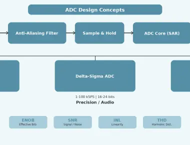
Ignoring PLL Jitter: Deriving a high frequency from a low-frequency crystal using a large multiplier (N) inherently amplifies phase noise (jitter). For high-precision ADC sampling or rigorous communication interfaces, excessive clock jitter will degrade the Signal-to-Noise Ratio (SNR) and increase bit error rates.
The clock tree is one of the largest consumers of dynamic power in a microcontroller. Dynamic power is proportional to frequency and the number of clocked nodes:
P_dynamic ∝ C × V² × f × α
Where C is capacitance, V is voltage, f is frequency, and α is the activity factor. Disabling clocks to unused peripherals (clock gating) is one of the most effective power-saving techniques available. Most microcontrollers provide RCC (Reset and Clock Control) registers that allow individual peripheral clocks to be enabled or disabled.
In low-power modes, the clock tree is progressively shut down:
The clock tree is the nervous system of every microcontroller. It determines how fast the CPU executes, how accurately peripherals time their operations, and how much power the system consumes. A solid understanding of PLLs, prescalers, clock domains, and their interactions is what separates working embedded systems from robust, production-ready ones.
When debugging timing issues, communication failures, or unexpected power consumption, the clock tree should be one of the first things you verify. A misconfigured prescaler or missing PLL lock wait can manifest as bugs that look like software issues but are fundamentally clock problems.
Quick Links
Legal Stuff