


Rate Monotonic Scheduling and Schedulability Analysis in RTOS
June 22, 2026
5 min
Real-time operating systems have transformed how we structure embedded firmware. Gone are the days when a bare-metal super-loop could handle the complexity of modern IoT devices, wearables, and industrial controllers. As systems grow — with multiple sensors, communication interfaces, displays, and safety requirements — the software architecture must evolve beyond linear polling. Task design patterns borrowed from general software engineering, adapted for RTOS primitives, provide the scaffolding for maintainable and reliable firmware.
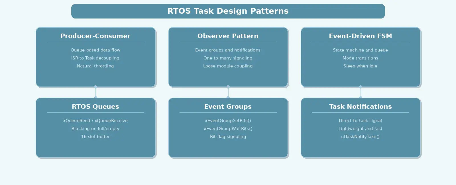
This article explores three foundational design patterns that every embedded developer should have in their toolkit: the producer-consumer pattern, the observer pattern, and event-driven state machines. Each maps cleanly to RTOS primitives like queues, task notifications, and timers.
The producer-consumer pattern is arguably the most important communication pattern in RTOS-based systems. It decouples data generation from data processing, allowing tasks to run at different rates without tight coupling.
Consider a system sampling an ADC at 1 kHz. A dedicated acquisition task produces samples. A processing task consumes them — perhaps running a digital filter or FFT. If these tasks share a global buffer with no synchronization, you get race conditions. The RTOS queue solves this elegantly.
+---------------------------+ +---------------------------+| ADC Task (Producer) | | Processing Task || Priority: High | | Priority: Medium || | | || 1. Read ADC | | 1. Block on queue || 2. Write to queue | ----> | 2. Receive sample || 3. Loop | | 3. Apply filter |+---------------------------+ +---------------------------+| Queue (10 slots) || [ ][ ][ ][ ][ ][ ]... |+---------------------------+
The queue acts as a buffer. If the producer outpaces the consumer, data is not lost — it waits in the queue. If the consumer runs faster, it blocks on the queue and yields the CPU to other tasks. This natural throttling is exactly what real-time systems need.
In FreeRTOS, the implementation is straightforward:
#define SAMPLE_QUEUE_LENGTH 16#define SAMPLE_QUEUE_ITEM sizeof(uint16_t)QueueHandle_t xSampleQueue;// In main() or initialization:// xSampleQueue = xQueueCreate(SAMPLE_QUEUE_LENGTH, SAMPLE_QUEUE_ITEM);void vADC_Task(void *pvParameters) {uint16_t adc_value;for (;;) {// Assumes ADC_Read_Blocking suspends the task until data is readyadc_value = ADC_Read_Blocking();// Send to queue, block if full (wait up to 100 ticks)if (xQueueSend(xSampleQueue, &adc_value, pdMS_TO_TICKS(100)) != pdPASS) {// Handle queue full error (e.g., log dropped sample)}}}void vProcessing_Task(void *pvParameters) {uint16_t sample;for (;;) {// Block indefinitely until data arrivesif (xQueueReceive(xSampleQueue, &sample, portMAX_DELAY) == pdPASS) {apply_filter(&sample);}}}
A key design decision is queue depth. Too shallow and you risk data overruns under burst conditions. Too deep and you waste RAM. A good rule of thumb: size the queue to hold enough items to cover the maximum expected processing latency at the production rate.
Performance Note: While queueing individual samples works well for moderate data rates, at high frequencies (e.g., >10 kHz ADC sampling), the per-sample RTOS API overhead becomes significant. For high-throughput scenarios, use DMA to fill an array and use an RTOS queue or task notification to pass a pointer to the buffer once it’s full.
ISR Context: If the producer is an interrupt handler rather than a task, you must use the ISR-safe API variants (
xQueueSendFromISR,xEventGroupSetBitsFromISR, etc.). These never block and use apxHigherPriorityTaskWokenflag to defer context switching to the end of the ISR.
The observer pattern enables one-to-many dependency between tasks. When one task changes state, all interested tasks are notified automatically. This is essential for building modular firmware where the sensor driver should not need to know about the display driver.
In an RTOS context, the observer pattern maps naturally to task notifications or event groups. While FreeRTOS task notifications are highly efficient for one-to-one signaling, event groups are better suited for one-to-many broadcasting and many-to-one synchronization.
+---------------------------+| Sensor Task || (Subject) || || 1. Read temperature || 2. Check threshold || 3. Notify observers |+---------------------------+|+------+------+------------------+| | |v v v+---------+ +-----------+ +--------------+| Display | | Logger | | Control || Task | | Task | | Task || | | | | || Update | | Write SD | | Adjust PWM || screen | | card | | duty cycle |+---------+ +-----------+ +--------------+
Here is a simplified implementation using FreeRTOS event groups:
#define EVT_TEMP_HIGH (1UL << 0)#define EVT_TEMP_LOW (1UL << 1)EventGroupHandle_t xSensorEvents;void vSensor_Task(void *pvParameters) {float temperature;for (;;) {temperature = read_temperature();if (temperature > TEMP_THRESHOLD_HIGH) {xEventGroupSetBits(xSensorEvents, EVT_TEMP_HIGH);} else if (temperature < TEMP_THRESHOLD_LOW) {xEventGroupSetBits(xSensorEvents, EVT_TEMP_LOW);}vTaskDelay(pdMS_TO_TICKS(1000));}}void vDisplay_Task(void *pvParameters) {EventBits_t bits;for (;;) {bits = xEventGroupWaitBits(xSensorEvents,EVT_TEMP_HIGH | EVT_TEMP_LOW,pdTRUE, // clear on exit (see note below)pdFALSE, // wait for any bitportMAX_DELAY);if ((bits & EVT_TEMP_HIGH) != 0) {display_warning("Overtemp!");} else if ((bits & EVT_TEMP_LOW) != 0) {display_warning("Undertemp!");}}}
Design Caveat: In this simplified example, the display task clears the event bit upon exit (
pdTRUE). If multiple observers (like a logger and a display) need to reliably receive the exact same edge-triggered event, having one task clear the bit can cause others to miss it if they aren’t concurrently blocked on the event group. For robust 1-to-N broadcasting, consider having the producer manage clearing the state bits, or use a publish-subscribe manager that distributes events to individual observer queues.
The beauty of this pattern is that the sensor task has no knowledge of its observers. You can add a logging task, a buzzer task, or a cloud-upload task as observers without modifying the sensor code. This is the essence of modular design.
Event-driven architectures combine the best of both previous patterns. Instead of polling flags in a super-loop, the system reacts to events by transitioning between states. This is particularly powerful in systems with multiple operating modes: boot, idle, active, fault, and sleep.
The state machine has a defined set of states, a set of events that trigger transitions, and actions executed during transitions. In an RTOS, events arrive via queue items, and the state machine task processes them sequentially.
+--------------------------------------------------+| System State Machine |+--------------------------------------------------+| || +------+ EVT_BUTTON +--------+ || | IDLE | --------------> | ACTIVE | || +------+ +--------+ || ^ | | || | EVT_TIMEOUT | | EVT_FAULT || +-------------------------+ v || +-------+ || | FAULT | || +-------+ || | || | EVT_RESET || v || +------+ || | IDLE | || +------+ |+--------------------------------------------------+
Implementation in C using an RTOS typically looks like:
typedef enum { STATE_IDLE, STATE_ACTIVE, STATE_FAULT } SystemState;typedef enum { EVT_BUTTON, EVT_TIMEOUT, EVT_FAULT, EVT_RESET } SystemEvent;QueueHandle_t xEventQueue;void vStateMachine_Task(void *pvParameters) {SystemState current_state = STATE_IDLE;SystemEvent event;for (;;) {if (xQueueReceive(xEventQueue, &event, portMAX_DELAY) == pdPASS) {switch (current_state) {case STATE_IDLE:if (event == EVT_BUTTON) {start_peripherals();current_state = STATE_ACTIVE;}break;case STATE_ACTIVE:if (event == EVT_FAULT) {shutdown_outputs();current_state = STATE_FAULT;} else if (event == EVT_TIMEOUT) {enter_low_power();current_state = STATE_IDLE;}break;case STATE_FAULT:if (event == EVT_RESET) {system_reset();}break;default:// Defensive programming: catch undefined statescurrent_state = STATE_FAULT;break;}}}}
The critical advantage: when no events are pending, the state machine task is blocked on the queue. The CPU enters idle task context, allowing low-power modes. This eliminates wasteful polling and naturally handles asynchronous inputs.
A real-world embedded system rarely uses just one pattern. Consider a smart thermostat:
+----------+ +-------+ +---------+| Temp |--->| PID |--->| Relay || Sensor | | Ctrl | | Control |+----------+ +---+---+ +---------+|+-----+-----+| |v v+----------+ +--------+| Display | | Cloud || Update | | Upload |+----------+ +--------+
The key insight is that these patterns compose. Queues connect producers to consumers. Event groups connect subjects to observers. The state machine orchestrates high-level behavior. Each pattern handles one dimension of the system’s complexity.
Not every RTOS offers the same primitives. FreeRTOS provides queues, semaphores, mutexes, task notifications, event groups, software timers, and message buffers. Zephyr adds workqueues, k_poll, and power management integration. ThreadX offers event flags, message queues, and block pools.
The mapping is consistent across RTOSes:
| Pattern | FreeRTOS Primitive | Zephyr Primitive |
|---|---|---|
| Producer-Consumer | Queue / MessageBuffer | k_msgq / k_fifo |
| Observer | EventGroup / TaskNotification | k_poll / k_event |
| Event-Driven | Queue + state machine | Zephyr SMF / k_work |
Choose the lightest primitive that meets your requirements. Task notifications are faster than semaphores for one-to-one observer relationships. Event groups work well when multiple event types must be signaled to multiple observers.
Task design patterns bring structure to embedded firmware. The producer-consumer pattern handles data flow with natural buffering. The observer pattern enables loose coupling between modules. Event-driven state machines manage complex mode transitions efficiently. Together, they form the architectural backbone of maintainable RTOS-based systems.
Start by identifying the data flow in your system. Map producers and consumers to queues. Identify state changes that need to broadcast updates — those are your observer relationships. Finally, look for mode transitions driven by events — those belong in a state machine. With these three patterns, your firmware will be modular, testable, and ready to evolve.
Quick Links
Legal Stuff