


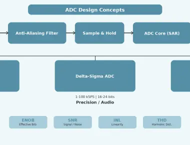
ADC Design Concepts for Embedded Systems
June 14, 2026
5 min
The Inter-Integrated Circuit (I2C) protocol is one of the most widely used communication buses in embedded systems. Developed by Philips Semiconductor (now NXP) in 1982, I2C connects low-speed peripherals — sensors, EEPROMs, RTCs, ADCs, and IO expanders — using just two wires. Its elegant addressing scheme, built-in acknowledgment, and multi-master support make it a go-to choice for board-level communication.
Despite its apparent simplicity, I2C has nuanced electrical and protocol-level details that regularly trip up engineers. Clock stretching, bus arbitration, and rise-time requirements caused by bus capacitance are common sources of intermittent failures. This article covers the protocol from the electrical layer up to transaction-level code.
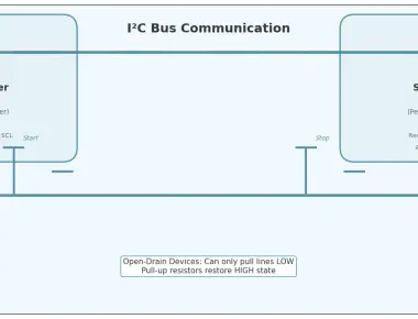
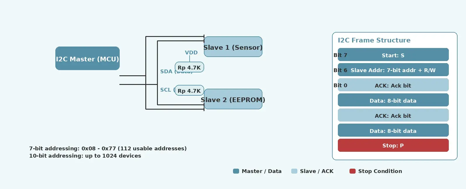
I2C uses two bidirectional open-drain lines: SDA (serial data) and SCL (serial clock). Both lines are pulled high by resistors (typically 2.2k to 10k ohms depending on bus speed and capacitance). Any device can pull a line low, but no device actively drives it high — the pull-up resistors handle that. This wired-AND configuration is the foundation of I2C’s multi-master capability and clock synchronization.
I2C Bus TopologyVDD|[Rp] Pull-up resistor|+------+------+-------------------+SDA ----------+----------+---------+------| |+-----+----+ +---+-----+| MCU | | Sensor || (Master) | | (Slave) |+-----+----+ +---+-----+| |SCL ----------+----------+---------+------| |+-----+----+ +---+-----+| EEPROM | | RTC || (Slave) | | (Slave) |+----------+ +---------+All devices share the same SDA and SCL lines.Each slave has a unique 7-bit address.
Every device on the bus is either a master or slave. The master generates the clock on SCL and initiates transactions. Slaves respond when addressed. The protocol supports multiple masters on the same bus, with arbitration ensuring that only one master controls the bus at a time.
The open-drain design means devices can only pull the bus LOW or release it (letting the pull-up resistor pull it HIGH). This has several critical implications:
Rise time is determined by the RC time constant. The bus capacitance (from traces, connectors, and device input capacitance, typically 10-40 pF per device) combined with the pull-up resistor forms an RC circuit. A 4.7k pull-up with 200 pF of bus capacitance gives a rise time of approximately 1 us — marginal for 400 kHz Fast Mode and completely inadequate for 1 MHz+ speeds.
Total bus capacitance is limited to 400 pF by the specification. At 100 kHz Standard Mode, longer traces and more devices may approach this limit, causing signal integrity issues. Solutions include reducing pull-up resistor values (increasing power consumption), using bus extenders/repeaters, or splitting the bus with multiplexers.
// Typical pull-up calculation for 400 kHz Fast Mode:// tr(max) = 300 ns (from I2C spec, Fast Mode)// C_bus = 200 pF (estimated from layout)// Rp(max) = tr / (0.8473 * C_bus)// = 300e-9 / (0.8473 * 200e-12)// = 1.77 kOhm minimum// Use 1.5 kOhm or 1.8 kOhm for margin
Every I2C transaction begins with a START condition and ends with a STOP condition. Between these framing signals, data is transferred in 8-bit bytes, each followed by a 9th acknowledge (ACK) bit.
Repeated START (Sr): A master can issue a repeated START without first issuing a STOP, allowing it to switch between slave addresses or change transfer direction within a single transaction. This is essential for register-based read operations.
I2C Write Transaction (Master -> Slave)S | Slave Addr + W | A | Data Byte 1 | A | Data Byte 2 | A | P---+----------------+---+-------------+---+-------------+---+---S = Start, P = Stop, A = ACK, R/W bit: 0=Write, 1=ReadI2C Register Read Transaction (Master <- Slave)S | Slave Addr + W | A | Reg Addr | A | Sr | Slave Addr + R | A | Data | NA | P---+----------------+---+----------+---+-----+----------------+---+------+-----+---Sr = Repeated Start, NA = NACK (master sends NACK on last byte)
The acknowledge protocol works as follows: after each byte, the receiving device pulls SDA LOW during the 9th clock pulse to acknowledge. If the receiver does not pull SDA low (NACK), the master knows the byte was not received — either the slave is not present, is busy, or has signaled an error.
The standard I2C address field is 7 bits wide, providing 128 possible addresses. Twelve of these are reserved, leaving 112 usable addresses (0x08 through 0x77). If you need more devices on a single bus, 10-bit addressing extends the address space to 1024 devices.
In 10-bit addressing, the first byte uses the special pattern 11110xx where xx are the upper two bits of the 10-bit address, followed by a second address byte for the lower 8 bits.
Standard 7-bit Address Frame:+-------+-----+---+---+---+---+---+---+----+| Start | A6 | A5| A4| A3| A2| A1| A0| R/W|+-------+-----+---+---+---+---+---+---+----+10-bit Address Frame:+-------+-----+-----+---+---+---+---+---+----+-------+-----+---+---+---+---+---+---+---+| Start | 1 | 1 | 1 | 1 | 0 |A9 |A8 | R/W| ACK | A7 | A6| A5| A4| A3| A2| A1| A0|+-------+-----+-----+---+---+---+---+---+----+-------+-----+---+---+---+---+---+---+---+
Common address conflicts arise when using multiple identical sensors that share a fixed I2C address. Solutions include using devices with address-select pins, I2C multiplexers (like the TCA9548A), or software workarounds on buses with limited device counts.
One of I2C’s unique features is clock stretching: a slave can hold SCL LOW after the master has released it, forcing the master to wait. This allows slow slaves to control the effective bus speed — a slave that needs more time to process a received byte simply stretches the clock before sending its ACK bit.
Clock Stretching TimingMaster SCL: +----+ +----+ +---------+| | | | | |SDA +----------+ +--Slave SCL: +----+ +----+ +----+| | | | | |SDA +----------+ +--|stretched|Slave holds SCL low here
Not all microcontrollers support clock stretching properly. Some I2C peripherals (particularly on Silicon Labs EFM32 and certain STM32 families) have known issues with clock stretching. When debugging mysterious I2C hangs, clock stretching support is one of the first things to verify.
When two masters attempt to start a transaction simultaneously, I2C’s wired-AND bus provides arbitration without data loss. Each master monitors SDA while transmitting. If a master sends a HIGH but reads a LOW (because another master is pulling the line down), it detects a collision and yields the bus.
Arbitration is bit-position-based: the master that first sends a LOW bit where the other sends a HIGH wins. Crucially, arbitration can only occur during address and data bytes — no device may win arbitration during START, STOP, or repeated START conditions.
Arbitration Example: Master A vs Master BMaster A sends: 1 0 1 1 0 0 1 0 (0xB2)Master B sends: 1 0 1 0 0 0 1 0 (0xA2)-------> collides hereSDA bus: 1 0 1 0 0 0 1 0 <- actual bus valueAt bit position 4, Master A sends '1' but reads '0'.Master A loses arbitration and releases the bus.Master B continues uninterrupted -- no data corruption.
The following example demonstrates a register read from a typical I2C sensor using STM32 register-level code:
#include <stdint.h>#include "stm32f4xx.h"#define I2C1_SDA_PIN PB7#define I2C1_SCL_PIN PB6#define SENSOR_ADDR 0x48 // 7-bit addresstypedef enum {I2C_OK = 0,I2C_ERR_NACK,I2C_ERR_TIMEOUT,I2C_ERR_BUS} i2c_status_t;/* Read a register from an I2C slave using Repeated START */i2c_status_t i2c_read_reg(uint8_t slave_addr, uint8_t reg_addr,uint8_t *rx_data, uint16_t len){uint32_t timeout;/* Wait until bus is free */timeout = 100000;while ((I2C1->SR2 & I2C_SR2_BUSY) && timeout--);if (timeout == 0) return I2C_ERR_BUS;/* Generate START condition */I2C1->CR1 |= I2C_CR1_START;timeout = 10000;while (!(I2C1->SR1 & I2C_SR1_SB) && timeout--);if (timeout == 0) return I2C_ERR_TIMEOUT;/* Send slave address + Write (R/W = 0) */I2C1->DR = (slave_addr << 1) & 0xFE;timeout = 10000;while (!(I2C1->SR1 & I2C_SR1_ADDR) && timeout--);if (timeout == 0) return I2C_ERR_TIMEOUT;/* Clear ADDR flag by reading SR1 then SR2 */(void)I2C1->SR1;(void)I2C1->SR2;/* Check for NACK */if (I2C1->SR1 & I2C_SR1_AF) {I2C1->SR1 &= ~I2C_SR1_AF;I2C1->CR1 |= I2C_CR1_STOP;return I2C_ERR_NACK;}/* Send register address */I2C1->DR = reg_addr;timeout = 10000;while (!(I2C1->SR1 & I2C_SR1_TXE) && timeout--);if (timeout == 0) return I2C_ERR_TIMEOUT;/* Wait for byte transfer complete */timeout = 10000;while (!(I2C1->SR1 & I2C_SR1_BTF) && timeout--);/* Generate Repeated START */I2C1->CR1 |= I2C_CR1_START;timeout = 10000;while (!(I2C1->SR1 & I2C_SR1_SB) && timeout--);/* Send slave address + Read (R/W = 1) */I2C1->DR = (slave_addr << 1) | 0x01;timeout = 10000;while (!(I2C1->SR1 & I2C_SR1_ADDR) && timeout--);if (timeout == 0) return I2C_ERR_TIMEOUT;/* Clear ADDR flag */(void)I2C1->SR1;(void)I2C1->SR2;/* Read data bytes */for (uint16_t i = 0; i < len; i++) {if (i == len - 1) {/* Last byte: send NACK then STOP */I2C1->CR1 &= ~I2C_CR1_ACK;I2C1->CR1 |= I2C_CR1_STOP;} else {/* More bytes coming: keep ACK enabled */I2C1->CR1 |= I2C_CR1_ACK;}timeout = 10000;while (!(I2C1->SR1 & I2C_SR1_RXNE) && timeout--);if (timeout == 0) return I2C_ERR_TIMEOUT;rx_data[i] = I2C1->DR;}return I2C_OK;}
Key details in this implementation: the ADDR flag is cleared by reading both SR1 and SR2 in sequence (a common source of bugs), the NACK/STOP sequence for the final byte must happen before reading the data register, and the Repeated START replaces a STOP+START pair for atomic register reads.
I2C defines several speed modes with different electrical and timing requirements:
I2C Speed Mode Comparison
| Mode | Max Speed | Rise Time | Drive Strength |
|---|---|---|---|
| Standard Mode | 100 kHz | 1000 ns | Standard |
| Fast Mode | 400 kHz | 300 ns | Standard |
| Fast Mode Plus | 1 MHz | 120 ns | Stronger |
| High Speed | 3.4 MHz | 40 ns | Stronger |
| Ultra Fast | 5 MHz | 50 ns | Push-pull (no ACK) |
Ultra Fast Mode (5 MHz) uses push-pull drivers instead of open-drain, which means it cannot support clock stretching or multi-master arbitration. It is unidirectional (write-only) and is typically used for driving LED controllers or DACs at high speed.
Bus lockup from interrupted transactions. If a master is reset mid-transaction, a slave may be holding SDA low (waiting for clock pulses that will never come). The recovery procedure is to toggle SCL manually (using GPIO bit-banging) up to 9 times until the slave releases SDA, then issue a STOP condition.
Incorrect pull-up values. Too weak (high resistance) and the rise time violates the spec at higher speeds. Too strong (low resistance) and the slave cannot pull the line low against the current — the low-level voltage exceeds Vil(max). Always calculate based on actual bus capacitance.
Missing ACK handling. Some drivers ignore the NACK flag and blindly continue reading. A NACK after the address byte means the slave is not responding — continuing to clock data produces garbage. Always check the AF (Acknowledge Failure) flag.
Clock stretching timeouts. If a slave stretches the clock indefinitely (due to a firmware bug), the master hangs. Implement a timeout on SCL low duration in your I2C driver to detect and recover from this condition.
I2C remains the most practical choice for connecting multiple low-speed peripherals on a shared two-wire bus. Its addressing scheme, built-in ACK protocol, and multi-master support solve real design problems that SPI and UART cannot. However, the protocol’s electrical layer — open-drain signaling, pull-up selection, and bus capacitance — demands careful attention. Understanding clock stretching, arbitration, and the Repeated START mechanism will help you write robust I2C drivers and debug the intermittent failures that plague many embedded designs.
Quick Links
Legal Stuff