

Zephyr MPU Setup for Memory Protection in Embedded Systems
August 29, 2026
4 min
Precise time synchronization is the backbone of modern distributed embedded systems. From industrial automation and automotive networks to telecom base stations and power grid protection, the ability to synchronize clocks across multiple devices to sub-microsecond accuracy enables deterministic control, sensor fusion, and coordinated actuation. IEEE 1588 Precision Time Protocol (PTP) is the de facto standard for this purpose.
This article examines the practical implementation of IEEE 1588 on embedded microcontrollers, covering the protocol mechanics, hardware timestamping requirements, software stack architecture, and common pitfalls that degrade synchronization accuracy.
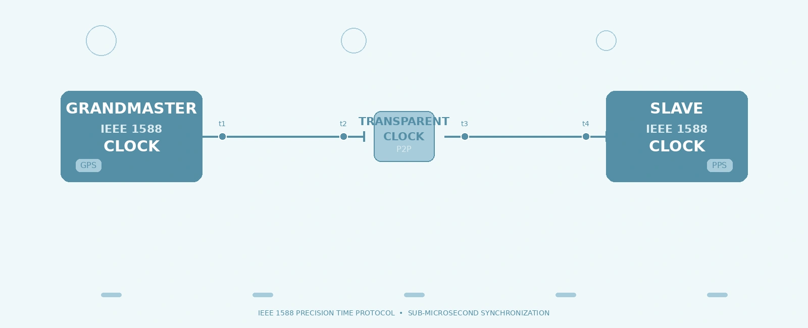
IEEE 1588 synchronizes a slave clock to a master clock through a message exchange that measures propagation delay and clock offset. The protocol operates in a hierarchical master-slave architecture with a single Grandmaster per domain.
The standard two-step end-to-end (E2E) delay mechanism uses four messages:
+-----------+ Sync (t1) +-----------+| Master | --------------> | Slave || | | || | Follow_Up (t1) | || | --------------> | || | | || | Delay_Req (t3) | || | <-------------- | || | | || | Delay_Resp (t4) | || | --------------> | |+-----------+ +-----------+
Timestamps captured:
Offset and delay calculation (assuming no Transparent Clocks):
offset = ((t2 - t1) - (t4 - t3)) / 2delay = ((t2 - t1) + (t4 - t3)) / 2
(Note: In networks with Transparent Clocks, the accumulated correctionField from the messages—representing switch residence times—must be subtracted during this calculation.)
The slave adjusts its local clock by the calculated offset. In practice, a servo loop (PI controller) filters the offset measurements to discipline the local oscillator.
For networks with transparent clocks (switches that measure and add residence time to a correction field), P2P delay measurement uses Pdelay_Req/Pdelay_Resp/Pdelay_Resp_Follow_Up messages between adjacent nodes. This isolates link delay from switch residence time, enabling better accuracy in multi-hop topologies.
+-----------+ +-----------+| Node A | | Node B || | Pdelay_Req | || | ----------------> | || | | || | Pdelay_Resp | || | <---------------- | || | | || | Pdelay_Resp_FU | || | <---------------- | |+-----------+ +-----------+
Software timestamping captures timestamps in the network driver or stack, introducing unpredictable latency from interrupt handling, context switching, and queueing. For sub-microsecond accuracy, timestamps must be captured at the MAC/PHY boundary.
Modern embedded Ethernet MACs (STM32 ETH, NXP ENET, TI CPSW, Xilinx Zynq GEM) include an IEEE 1588 Timestamping Unit:
+---------------------------+| Application Layer || (PTP Stack / linuxptp) |+------------+--------------+|+------------v--------------+| Network Stack || (lwIP / Linux kernel) |+------------+--------------+|+------------v--------------+| MAC Driver || - TSU register access || - PHC clock control |+------------+--------------+|+------------v--------------+| Ethernet MAC || +----------------------+ || | Timestamping Unit | || | - Tx timestamp regs | || | - Rx timestamp regs | || | - PTP event detect | || +----------------------+ || +----------------------+ || | PTP Hardware Clock | || | (PHC) / Timer | || +----------------------+ |+------------+--------------+|+------------v--------------+| PHY / RGMII / RMII |+---------------------------+
The PHC is a free-running counter (typically 64-bit, nanosecond resolution) that serves as the local time reference. The PTP stack disciplines the PHC frequency and phase via:
clock_adjtime() with the freq field of struct timex.clock_adjtime() with the offset field, or clock_settime() for a hard step.On Linux, the PHC is exposed via /dev/ptpX and controlled via character device ioctls (like PTP_CLK_GETCAPS) or POSIX clock APIs (clock_adjtime). Network interface timestamping is configured separately using socket ioctls (SIOCSHWTSTAMP, SIOCGHWTSTAMP) applied to the network interface.
On bare-metal (FreeRTOS, Zephyr, bare metal), the MAC driver provides equivalent register-level access to the TSU and timer registers.
A typical embedded PTP stack consists of:
+----------------------------------------------------+| Application || - Configuration (profile, domain, intervals) || - Monitoring (offset, delay, servo state) |+----------------------------------------------------+| PTP Protocol Engine || - State machine (Listening, Master, Slave, ...) || - Message construction/parsing (Sync, Follow_Up, || Delay_Req, Delay_Resp, Announce, Pdelay_*) || - BMCA (Best Master Clock Algorithm) || - Servo loop (PI controller for clock discipline) |+----------------------------------------------------+| Transport Layer || - UDP/IPv4, UDP/IPv6, IEEE 802.3 (L2) || - Multicast/unicast handling |+----------------------------------------------------+| Hardware Abstraction Layer (HAL) || - TSU register access (capture Tx/Rx timestamps) || - PHC read/adjust (frequency, phase) || - PPS output control || - Interrupt handling (Tx/Rx timestamp ready) |+----------------------------------------------------+| Ethernet MAC + PHY |+----------------------------------------------------+
| Stack | License | Target | Notable Features |
|---|---|---|---|
| linuxptp (ptp4l, phc2sys) | GPLv2 | Linux | Full IEEE 1588-2019, P2P/E2E, hardware/software timestamping, multiple domains, unicast |
| PTPd | BSD | Linux, bare-metal | Lightweight, Ordinary/Boundary clock, P2P/E2E |
| gPTP stack (IEEE 802.1AS) | BSD | Linux, Zephyr, FreeRTOS | TSN profile, mandatory hardware timestamping |
| Zephyr PTP | Apache 2.0 | Zephyr RTOS | Ordinary clock, hardware timestamping via net_mgmt API |
| FreeRTOS+TCP PTP | MIT | FreeRTOS | Basic PTP support, software timestamping option |
For bare-metal STM32/NXP/TI MCUs, vendors provide HAL-level PTP examples (STM32Cube PTP, MCUXpresso SDK PTP, TI Processor SDK PTP) that demonstrate TSU register programming.
The single most common cause of poor accuracy is relying on software timestamps. Verify hardware timestamping is enabled:
// Linux: enable hardware timestamping on the network interfacestruct ifreq ifr;memset(&ifr, 0, sizeof(ifr));strncpy(ifr.ifr_name, "eth0", IFNAMSIZ - 1);struct hwtstamp_config config = {.flags = 0,.tx_type = HWTSTAMP_TX_ON,.rx_filter = HWTSTAMP_FILTER_PTP_V2_EVENT,};ifr.ifr_data = (void *)&config;if (ioctl(sock, SIOCSHWTSTAMP, &ifr) < 0) {perror("SIOCSHWTSTAMP");}
On bare metal, ensure the MAC TSU interrupt is enabled and the driver captures the timestamp from the Tx/Rx timestamp registers immediately on interrupt.
The servo loop must correctly translate offset measurements to PHC adjustments. Common errors:
The delay calculation inherently assumes symmetric forward and reverse path delays. Asymmetry introduces a static offset error. There are two main types of asymmetry:
delayAsymmetry property in the PTP stack). As a design practice, use symmetrical PHYs and matched PCB trace lengths to minimize this asymmetry at the hardware level.Even with hardware timestamping, the interrupt handler must read the timestamp register before it is overwritten by the next event. On high-traffic links:
BMCA flapping can occur if clock quality attributes (like GPS lock status) fluctuate, causing the network to repeatedly switch Grandmasters. (BMCA is deterministic; it does not flap simply due to tied priorities, as port identity acts as a strict tie-breaker). Fix:
priority1 values to force a strict hierarchy (e.g., 128 for primary, 129 for backup)clockClass values to differentiate (e.g., 6 = locked to primary reference, 7 = holdover within specification, 248 = default free-running)unicast_master_table for static Grandmaster assignment in critical deploymentsUse a Time Interval Counter (TIC) or oscilloscope to measure PPS alignment between Grandmaster and slave:
+-------------+ +-------------+| Grandmaster | | Slave || (PPS out) | | (PPS out) |+------+------+ +------+------+| || PPS Ch1 PPS Ch2 || +----------+ |+------>| TIC / |<-------+| Scope |+----------+Measure Δt
Target accuracy tiers:
Implementing IEEE 1588 PTP on embedded systems demands hardware timestamping at the MAC/PHY layer, a disciplined PTP hardware clock, and a well-tuned servo loop. Software-only timestamping cannot achieve sub-microsecond accuracy. The protocol mechanics are straightforward — four timestamps yield offset and delay — but the devil is in the details: asymmetric path delays, interrupt latency, servo stability, and Grandmaster selection.
Key takeaways:
Quick Links
Legal Stuff