

Optimizing Cortex-M Tail-Chaining for Sub-Microsecond Latency
August 15, 2026
5 min
The Cortex-M SysTick timer is the backbone of timekeeping in almost every RTOS and bare-metal scheduler targeting ARM Cortex-M cores. It’s a 24-bit down-counter located in the System Control Space (SCS) alongside the NVIC, clocked from the core clock (optionally divided by 8), and tied to a dedicated exception vector (Exception #15). Despite its simplicity, misconfiguration of SysTick is a common source of subtle timing bugs — missed ticks, jitter, or complete scheduler failure.
This article walks through the SysTick register map, clock source selection, reload value calculation, interrupt setup, and common pitfalls when using SysTick for RTOS ticks or bare-metal periodic timing.
The SysTick timer exposes four 32-bit registers in the System Control Space (SCS) at base address 0xE000E010:
+--------+---------------+-------------------+-------------------+| Offset | Register | Description | Key Bits |+========+===============+===================+===================+| 0x00 | SYST_CSR | Control & Status | ENABLE (0) || | | | TICKINT (1) || | | | CLKSOURCE (2) || | | | COUNTFLAG (16) |+--------+---------------+-------------------+-------------------+| 0x04 | SYST_RVR | Reload Value | RELOAD[23:0] |+--------+---------------+-------------------+-------------------+| 0x08 | SYST_CVR | Current Value | CURRENT[23:0] |+--------+---------------+-------------------+-------------------+| 0x0C | SYST_CALIB | Calibration | TENMS[23:0] || | | | SKEW (30) || | | | NOREF (31) |+--------+---------------+-------------------+-------------------+
Key register behaviors:
The CLKSOURCE bit in SYST_CSR selects the clock input:
| CLKSOURCE | Source | Frequency |
|---|---|---|
| 0 | External reference clock (typically core_clk / 8) | Core clock ÷ 8 |
| 1 | Processor clock (core clock) | Core clock |
Always use CLKSOURCE = 1 (processor clock) unless you have a specific reason to use the divided reference. The reference clock frequency is implementation-defined and may not be exactly core_clk/8. Using the processor clock gives you deterministic, calculable timing.
// Use processor clock (core clock)#define SYST_CSR_CLKSOURCE_Msk (1UL << 2)SYST_CSR |= SYST_CSR_CLKSOURCE_Msk;
The reload value determines the period. SysTick counts down from RELOAD to 0, then reloads. The number of clock cycles per period is RELOAD + 1.
period_cycles = RELOAD + 1RELOAD = (core_clock_hz / desired_freq_hz) - 1
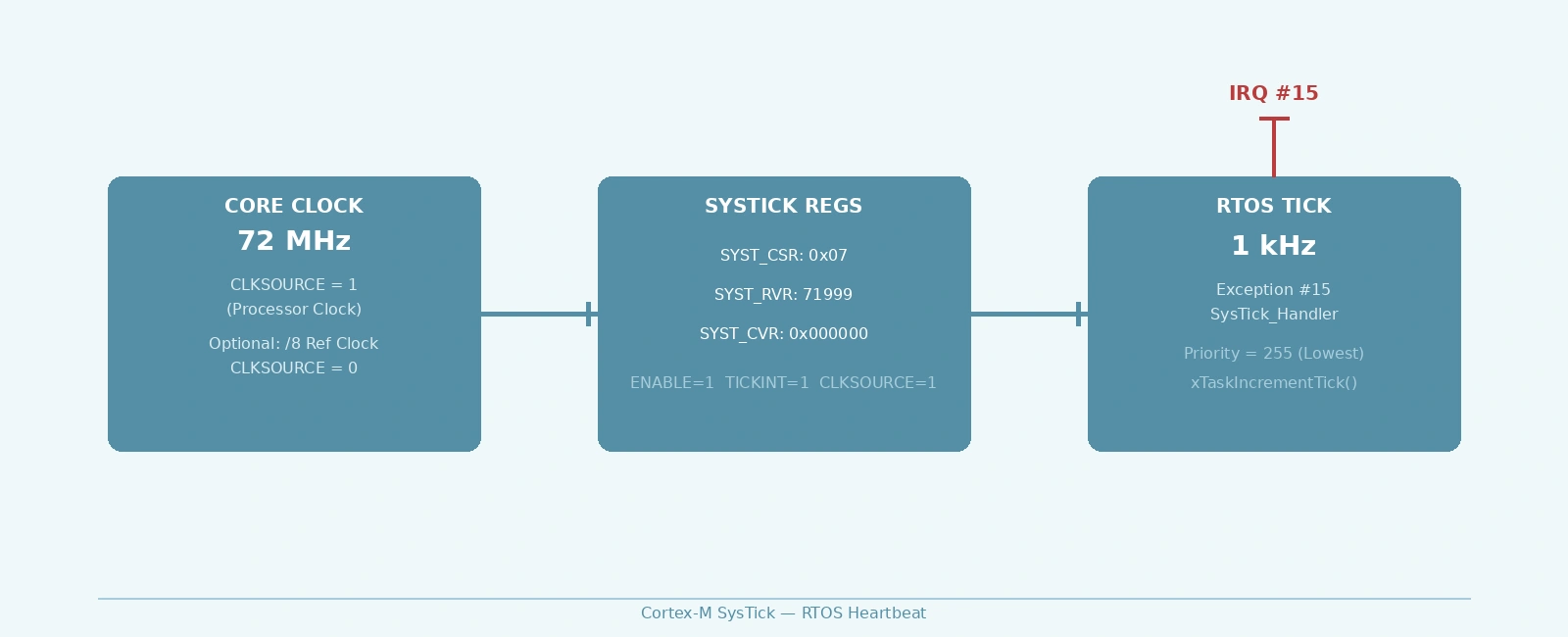
Example: 1 kHz tick at 72 MHz
RELOAD = (72,000,000 / 1,000) - 1 = 71,999 = 0x0001193F
Example: 1 kHz tick at 168 MHz (STM32F4) with /8 prescaler
RELOAD = (168,000,000 / 8 / 1,000) - 1 = 20,999 = 0x00005207SYST_CSR &= ~SYST_CSR_CLKSOURCE_Msk; // Use external reference clock (divided by 8)
Maximum reload value: 0x00FFFFFF (24-bit). At 72 MHz with /8 prescaler, max period ≈ 1.86 seconds.
Enable the SysTick exception by setting TICKINT (bit 1) in SYST_CSR:
#define SYST_CSR_ENABLE_Msk (1UL << 0)#define SYST_CSR_TICKINT_Msk (1UL << 1)#define SYST_CSR_CLKSOURCE_Msk (1UL << 2)void systick_init(uint32_t reload) {SYST_RVR = reload; // Set reload valueSYST_CVR = 0; // Clear current valueSYST_CSR = SYST_CSR_CLKSOURCE_Msk | // Processor clockSYST_CSR_TICKINT_Msk | // Enable interruptSYST_CSR_ENABLE_Msk; // Enable counter}
The SysTick exception handler is SysTick_Handler (Exception #15). In an RTOS context, this calls the tick increment function:
void SysTick_Handler(void) {// RTOS tick hookxPortSysTickHandler(); // FreeRTOS// osSystickHandler(); // CMSIS-RTOS2}
Priority: SysTick should typically run at the lowest priority (255 on Cortex-M3/M4/M7) to avoid preempting higher-priority interrupts. Configure via NVIC:
NVIC_SetPriority(SysTick_IRQn, 0xFF); // Lowest priority
Wrong: SYST_RVR = core_hz / tick_hz;
Right: SYST_RVR = (core_hz / tick_hz) - 1;
The counter counts from RELOAD down to 0 inclusive — that’s RELOAD + 1 cycles.
If you don’t write to SYST_CVR before enabling, the counter starts from a random power-on value, causing a wildly incorrect first period.
SYST_CVR = 0; // Must clear before enabling
The CLKSOURCE = 0 reference clock is not guaranteed to be core_clk/8. Some vendors implement it differently. Always verify in the device datasheet or use CLKSOURCE = 1.
If you poll COUNTFLAG in a loop, reading SYST_CSR clears it. This creates a race where you might miss a tick if an interrupt or another task also reads SYST_CSR between the tick and your check.
// Unreliable: reading CSR clears COUNTFLAGwhile (!(SYST_CSR & (1 << 16))) { /* wait */ }// The flag is now cleared by the read in the while condition!
Better: use the interrupt, or if polling, accept that reading CSR consumes the flag.
Setting SysTick priority higher than application interrupts causes the RTOS tick to preempt critical sections, breaking atomic operations. Always use the lowest priority.
For timestamping without periodic interrupts, configure SysTick with maximum reload:
void systick_freerun_init(void) {SYST_RVR = 0x00FFFFFF; // Max 24-bit valueSYST_CVR = 0;SYST_CSR = SYST_CSR_CLKSOURCE_Msk | SYST_CSR_ENABLE_Msk; // No TICKINT}// Read timestamp (down-counter)// Note: When calculating deltas across wraps, calculate the delta in ticks// first, then convert to microseconds to avoid non-power-of-2 wrap issues.uint32_t timestamp_us(void) {uint32_t elapsed_ticks = 0x00FFFFFF - SYST_CVR;return elapsed_ticks / (SystemCoreClock / 1000000);}// Or as up-counteruint32_t timestamp_ticks(void) {return 0x00FFFFFF - SYST_CVR;}
This gives a ~0.23 second wraparound at 72 MHz (core clock). For longer periods, chain with a software counter in a lower-frequency timer.
On dual-core Cortex-M devices (e.g., STM32H7), each core has its own SysTick timer. They are not synchronized by hardware. For cross-core time sync, use a shared hardware timer (TIM, LPTIM) or a hardware semaphore with a common timebase.
0xE000E010 with four registersCLKSOURCE = 1 (processor clock) for deterministic timingRELOAD = (f_clk / f_tick) - 1 — don’t forget the -1SYST_CVR before enablingTICKINT bit, set priority to lowest (0xFF)xPortSysTickHandler for FreeRTOS)xPortSysTickHandler implementationQuick Links
Legal Stuff