

Fixing Zephyr BMI160 I2C Timeout on STM32
September 20, 2026
5 min
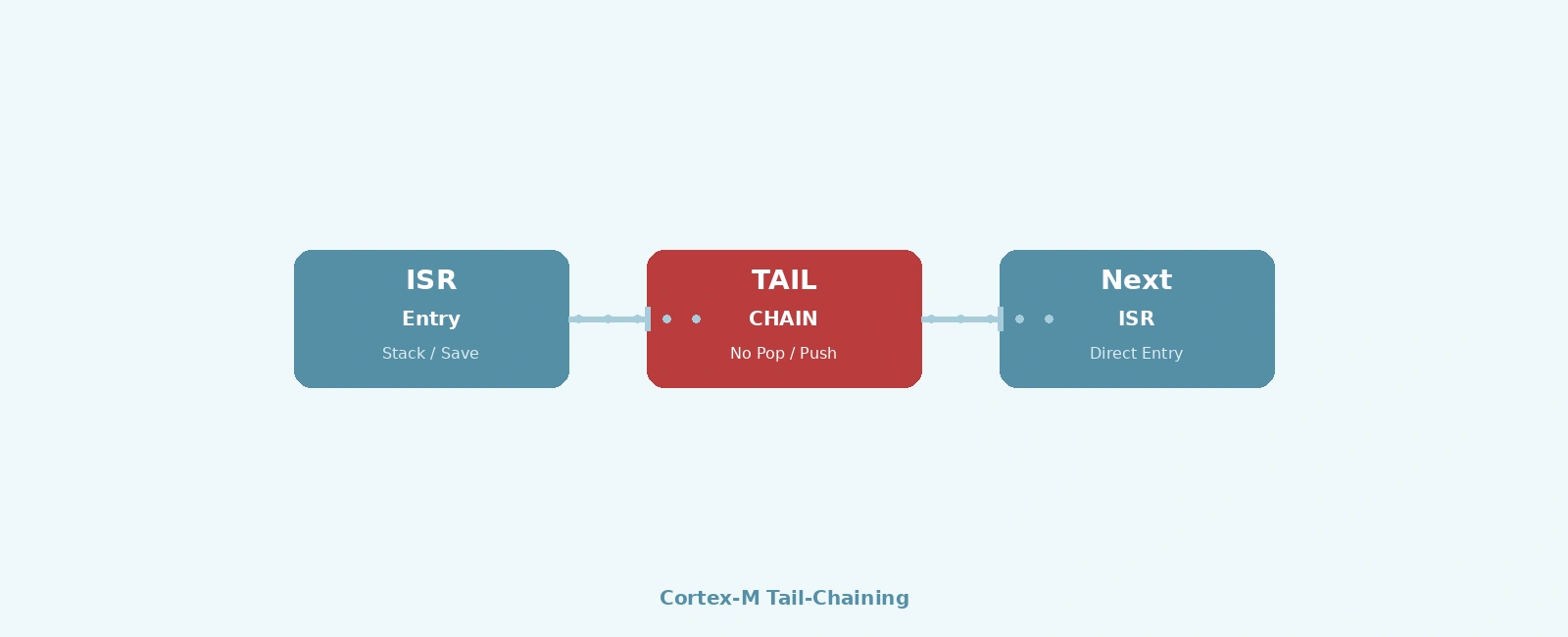
Tail-chaining is one of the most underappreciated latency optimizations in the Cortex-M architecture. When two interrupts fire back-to-back with compatible priorities, the NVIC skips the full register pop/push sequence and vectors directly from the first ISR to the second. On a Cortex-M4 at 168 MHz, this drops interrupt-to-interrupt latency from ~24 cycles to ~6 cycles — a 75% reduction that can determine whether your DMA completion handler meets its deadline or your motor control loop stays in sync.
The mechanism is simple in principle: when an ISR completes, the NVIC checks for pending interrupts. If a pending interrupt has sufficient priority to preempt the execution state the processor is returning to (e.g., returning to Thread mode), the processor performs a “tail-chained” entry. It does not pop R0-R3, R12, LR, PC, xPSR from the stack. Instead, it loads the new ISR’s vector address, modifies the stack frame slightly if necessary (such as updating the stacked PC), and begins executing the next handler.
+--------------------------------------------------+| Standard Interrupt Entry/Exit |+--------------------------------------------------+| ISR A Entry | ISR A Exit || Push R0-R3, R12, | Pop R0-R3, R12, || LR, PC, xPSR (8 regs)| LR, PC, xPSR (8 regs) || ~12 cycles | ~12 cycles || | || TOTAL: ~24 cycles | No tail-chaining |+--------------------------------------------------++--------------------------------------------------+| Tail-Chained Transition |+--------------------------------------------------+| ISR A Entry | ISR A Exit || Push R0-R3, R12, | (NVIC detects || LR, PC, xPSR | pending ISR B) || ~12 cycles | || | Tail-chain to ISR B || | (vector fetch + enter) || | ~6 cycles (no stacking) || | || ISR B executes | ISR B Exit || (uses existing | Pop R0-R3, R12, || stack frame) | LR, PC, xPSR || | ~12 cycles || | || TOTAL: ~30 cycles | vs ~48 cycles for two || for two ISRs | separate entries |+--------------------------------------------------+
A common misconception is that interrupts must have different priorities to tail-chain. In reality, assigning different preemption priorities encourages preemption, which breaks tail-chaining.
If a higher-priority interrupt arrives while a lower-priority ISR is executing, the NVIC immediately preempts the current ISR. This costs a full 12-cycle stack push. When the higher-priority ISR finishes, it must perform a full 12-cycle stack pop to resume the preempted ISR. This costs 24 cycles of overhead.
To maximize tail-chaining, assign the same preemption priority to high-speed peripherals that do not strictly need to preempt one another:
/* Priority scheme maximizing tail-chaining among high-speed peripherals *//* Lower numerical value = higher priority on Cortex-M */#define IRQ_PRI_HIGH_SPEED 1 /* Grouped together to force tail-chaining */#define IRQ_PRI_USART1 2 /* UART RX/TX */#define IRQ_PRI_SYSTICK 7 /* Lowest on a 3-bit system: RTOS tick */NVIC_SetPriority(DMA1_Stream0_IRQn, IRQ_PRI_HIGH_SPEED);NVIC_SetPriority(ADC1_IRQn, IRQ_PRI_HIGH_SPEED);NVIC_SetPriority(TIM1_CC_IRQn, IRQ_PRI_HIGH_SPEED);NVIC_SetPriority(USART1_IRQn, IRQ_PRI_USART1);NVIC_SetPriority(SysTick_IRQn, IRQ_PRI_SYSTICK);
With this scheme, if a DMA completion and an ADC conversion fire simultaneously (or one fires while the other is executing), they will not preempt each other. The first will execute, and upon completion, the NVIC will tail-chain directly into the second, saving 18 cycles. If DMA (priority 0) and ADC (priority 1) were used, the DMA would preempt the ADC, forcing a full context save and restore.
On Cortex-M3/M4/M7, the 8-bit priority register only has its upper N bits implemented (e.g., 3 or 4 bits). The remaining lower bits are unimplemented and always read as zero. The AIRCR.PRIGROUP field splits the implemented bits between preemption priority (group priority) and sub-priority.
NVIC Priority Register (8 bits, 3 bits implemented):[ Bit7 | Bit6 | Bit5 | Bit4 | Bit3 | Bit2 | Bit1 | Bit0 ][ Implemented (3 bits) | Unimplemented (5 bits, RAZ) ]Default PRIGROUP=0: all 3 bits are preemption priority, 0 sub-priority.PRIGROUP=5: 2 bits preemption, 1 bit sub-priority.PRIGROUP=6: 1 bit preemption, 2 bits sub-priority.
Sub-priority determines the order in which multiple pending interrupts of the same preemption priority are serviced. All such interrupts will sequentially tail-chain into each other, with the lowest sub-priority value (highest sub-priority) executing first.
Late-arrival is a separate optimization from tail-chaining, but the two work together to minimize total overhead.
If a higher-priority interrupt arrives during the 12-cycle stacking sequence of a lower-priority ISR, the NVIC continues the memory writes (because the saved context is the same — Thread mode state) but redirects the vector fetch to the higher-priority interrupt instead.
Timeline:T=0: ISR A (prio 2) triggered, stacking begins (saving Thread mode state)T=4: ISR B (prio 0) triggered — LATE ARRIVALT=4-12: NVIC redirects vector fetch to ISR B, stacking completesT=12: ISR B begins executingT=...: ISR B exits. ISR A is still pending.ISR A has higher priority than Thread mode → tail-chains.
The late-arrival optimization avoids wasting the stacking already in progress. When ISR B finishes, the processor would normally return to Thread mode, but ISR A is still pending with sufficient priority, so it tail-chains. The combination of both optimizations means neither a redundant stack push nor a redundant pop occurs.
If a higher-priority interrupt arrives after the current ISR has already begun executing, it immediately preempts it. The NVIC pushes a new stack frame containing the lower-priority ISR’s state. When returning, the higher-priority ISR must pop this frame to resume the lower-priority ISR. This cannot be tail-chained.
If the peripheral’s interrupt enable bit is clear, or NVIC_DisableIRQ() was called, the interrupt never reaches the pending state. Masking via PRIMASK or BASEPRI will also delay interrupts from becoming active until unmasked.
The most direct measurement uses a GPIO toggle at ISR entry and a logic analyzer:
#define PIN_DMA (1U << 5) /* PA5 — DMA ISR indicator */#define PIN_ADC (1U << 6) /* PA6 — ADC ISR indicator */void DMA1_Stream0_IRQHandler(void) {GPIOA->BSRR = PIN_DMA; /* PA5 rising edge = ISR entry *//* ... DMA handling ... */GPIOA->BSRR = (PIN_DMA << 16); /* PA5 falling edge = ISR exit */}void ADC1_IRQHandler(void) {GPIOA->BSRR = PIN_ADC; /* PA6 rising edge = ADC ISR entry *//* ... ADC handling ... */GPIOA->BSRR = (PIN_ADC << 16); /* PA6 falling edge = ADC ISR exit */}
With a 1 GS/s logic analyzer, you’ll see:
For cycle-accurate measurement without external gear, use the DWT cycle counter:
/* Enable DWT cycle counter (Cortex-M3/M4/M7/M33) */CoreDebug->DEMCR |= CoreDebug_DEMCR_TRCENA_Msk;DWT->CTRL |= DWT_CTRL_CYCCNTENA_Msk;uint32_t cycles_start, cycles_end;void DMA1_Stream0_IRQHandler(void) {cycles_start = DWT->CYCCNT;GPIOA->BSRR = (1 << 5);/* ... */cycles_end = DWT->CYCCNT;GPIOA->BSRR = ((1 << 5) << 16);/* Store delta for analysis */dma_isr_cycles = cycles_end - cycles_start;}void ADC1_IRQHandler(void) {uint32_t entry_cycles = DWT->CYCCNT;/* The gap from previous ISR exit to this entry: */adc_tail_chain_gap = entry_cycles - cycles_end; /* Should be ~6-8 if chained */GPIOA->BSRR = (1 << 6);/* ... */}
FreeRTOS on Cortex-M uses BASEPRI to mask interrupts up to configMAX_SYSCALL_INTERRUPT_PRIORITY. On a device with 3 implemented priority bits, configLIBRARY_MAX_SYSCALL_INTERRUPT_PRIORITY = 5 means library-level priority 5 (NVIC value 5 << (8-3) = 0xA0). This means:
taskENTER_CRITICAL() / taskEXIT_CRITICAL() and inside FreeRTOS API calls. They pend in the background. When the critical section exits and BASEPRI is cleared, all pending interrupts will fire and tail-chain into one another based on priority.Practical rule: Group your highest-throughput, latency-critical peripheral interrupts (DMA, ADC, high-speed timers) at the same preemption priority (if they don’t require FreeRTOS API access) or at least manage their grouping logically. This allows them to tail-chain rather than preempting one another.
/* FreeRTOSConfig.h typical values */#define configPRIO_BITS 3 /* 3 bits = 8 priority levels (0-7) */#define configLIBRARY_MAX_SYSCALL_INTERRUPT_PRIORITY 5 /* Priority 5 = syscall mask */#define configKERNEL_INTERRUPT_PRIORITY 7 /* SysTick, PendSV at lowest *//* Group high-speed peripherals at the same preemption priority to force tail-chaining */#define IRQ_PRI_HIGH_SPEED 0#define IRQ_PRI_UART 5 /* At syscall mask - uses xQueueSendFromISR */#define IRQ_PRI_I2C 6
On Armv8-M (Cortex-M33, M55, M85), TrustZone adds Secure/Non-secure state. Tail-chaining works within a security state but not across the Secure/Non-secure boundary. A Non-secure ISR cannot tail-chain into a Secure ISR (or vice versa) because the transition requires the Secure Gateway (SG) veneer and state save/restore.
Secure ISR (prio 1) --> Tail-chain --> Secure ISR (prio 2) ✓ WORKSNon-secure ISR (prio 1) --> Tail-chain --> Non-secure ISR (prio 2) ✓ WORKSNon-secure ISR (prio 1) --> Tail-chain --> Secure ISR (prio 2) ✗ BLOCKEDSecure ISR (prio 1) --> Tail-chain --> Non-secure ISR (prio 2) ✗ BLOCKED
The NSC (Non-secure Callable) entry adds ~20-30 cycles for the domain crossing. If your application mixes Secure and Non-secure interrupts, group them by security domain in the priority scheme to preserve tail-chaining within each domain.
| Factor | Effect on Tail-Chaining |
|---|---|
| Pending IRQ has sufficient priority vs. return state | Enables tail-chaining |
| Higher-priority IRQ preempts running ISR | Causes preemption (breaks tail-chaining) |
| Same preemption priority group | Forces tail-chaining instead of preemption |
| Late-arrival during stacking | Separate optimization; tail-chaining follows |
| FreeRTOS critical section (BASEPRI) | Delays interrupts; tail-chains upon exit |
| TrustZone Secure↔Non-secure | Blocks cross-domain tail-chaining |
Actionable takeaways:
Tail-chaining isn’t a feature you enable — it’s a behavior you design for through priority assignment. The hardware does the rest automatically. The 18-cycle savings per chained interrupt adds up fast in a system handling thousands of interrupts per second.
Quick Links
Legal Stuff