

Fixing Zephyr BMI160 I2C Timeout on STM32
September 20, 2026
5 min
UART DMA overrun errors are a frequent source of data corruption and silent communication failures in STM32-based systems. The symptom is often subtle: the UART appears to work initially, then starts dropping bytes or producing garbage after sustained traffic. The root cause is almost always a timing mismatch between the UART peripheral filling its receive data register and the DMA engine draining it.
This article covers the complete problem-solution cycle: why overrun happens, how to detect it in both HAL and LL drivers, the exact recovery sequence, and prevention strategies that work in production.
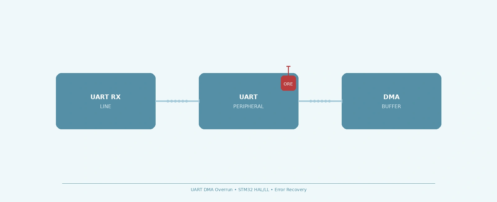
An overrun error (ORE) occurs when the UART shift register completes receiving a new byte, but the previous byte in the receive data register (RDR or DR) has not yet been read. In DMA mode, the DMA controller is responsible for reading the data register and writing to memory. If the DMA transfer does not complete before the next byte arrives, the hardware sets the ORE flag and the incoming byte is lost.
The STM32 reference manual (e.g., RM0090) states: “An overrun error occurs when a character is received when RXNE has not been reset.” The new byte is discarded, and the data currently in the data register is retained.
This is not a software bug — it is a hardware timing violation. The fix requires understanding the timing budget and ensuring the DMA path meets it.
Three primary factors cause UART DMA overrun:
At 921600 baud with 8N1 framing, each byte takes approximately 10.85 us on the wire. The DMA must read RDR and write to SRAM within this window. On an STM32F4 at 168 MHz, a single DMA transfer takes ~3-5 clock cycles plus bus arbitration. That is fast enough in isolation, but add:
The budget shrinks rapidly.
STM32 DMA controllers have multiple channels/streams sharing a single bus matrix. UART RX DMA typically uses a low-priority channel. If a high-priority channel (e.g., ADC DMA, SPI DMA, or memory-to-memory transfer) runs concurrently, the UART RX DMA may be stalled long enough for the next byte to arrive.
In non-circular mode, the DMA transfer complete (TC) interrupt must reconfigure the DMA for the next buffer. If the TC interrupt is delayed (higher-priority ISR, critical section, WFI sleep), the DMA sits idle while UART bytes pile up in RDR.
Circular DMA eliminates the TC interrupt reconfiguration latency. Double buffering (using HT and TC interrupts to ping-pong between two halves) gives the application a full half-buffer time to process data.
// STM32 HAL - Circular DMA with IDLE line detection (STM32L4/F7/H7/G4/F4)#define UART_RX_BUF_SIZE 256#define UART_RX_HALF_SIZE (UART_RX_BUF_SIZE / 2)static uint8_t uart_rx_buf[UART_RX_BUF_SIZE];static volatile uint16_t rx_write_idx = 0;void HAL_UARTEx_RxEventCallback(UART_HandleTypeDef *huart, uint16_t Size) {if (huart->Instance == USART2) {// Size is the absolute number of bytes received since reception started.// In circular mode, it corresponds to our current write index.rx_write_idx = (Size == UART_RX_BUF_SIZE) ? 0 : Size;}}void uart_dma_init_circular(UART_HandleTypeDef *huart) {// Start circular DMA reception with IDLE line detection.// HAL_UARTEx_ReceiveToIdle_DMA internally enables the IDLE interrupt.HAL_UARTEx_ReceiveToIdle_DMA(huart, uart_rx_buf, UART_RX_BUF_SIZE);// Disable DMA half-transfer interrupt if not needed// __HAL_DMA_DISABLE_IT(huart->hdmarx, DMA_IT_HT);}
Trade-off: Requires IDLE line detection (STM32F4/F7/H7/L4+) or manual HT/TC handling. Slightly more complex buffer management.
If circular DMA is not an option (older F1/F0), raise the UART RX DMA channel priority to Very High and isolate it from other DMA traffic.
// STM32F1xx LL - Set DMA channel priority to Very HighLL_DMA_SetChannelPriorityLevel(DMA1, LL_DMA_CHANNEL_5, LL_DMA_PRIORITY_VERYHIGH);// Ensure no other Very High priority channels exist// Move ADC/SPI DMA to High or Medium
Trade-off: Only helps if contention is the bottleneck. Does not fix baud-rate-exceeds-latency cases.
The most robust fix: let the UART signal the sender to pause when DMA cannot keep up. Requires RTS/CTS pins and a cooperating sender.
// Enable hardware flow control in HALhuart->Init.HwFlowCtl = UART_HWCONTROL_RTS_CTS;HAL_UART_Init(huart);// In LLLL_USART_SetHWFlowCtrl(USART2, LL_USART_HWCONTROL_RTS_CTS);
Trade-off: Requires 2 extra pins and a sender that respects CTS. Not viable for fixed-pin designs or legacy protocols.
If the TC interrupt handler is the bottleneck, optimize it:
NVIC_SetPriority to ensure UART DMA TC interrupt has appropriate priorityHAL_Delay() or blocking calls in ISRsWhen an overrun is detected, the UART peripheral enters a locked error state. To resume reception, a specific recovery sequence must be executed. The exact steps depend on whether you are using the HAL or LL drivers.
For bare metal or LL driver implementations, you must manually execute the full sequence in order. Skipping any step (such as re-enabling DMA before clearing ORE) can leave the peripheral in a stuck state.
Note on V1 vs V2 USART: STM32F1/F4 use V1 USART (SR/DR registers), where ORE is cleared by reading SR then DR. STM32F7/H7/L4/G4 use V2 USART (ISR/ICR/RDR registers), where ORE is cleared by writing to ICR. The example below targets V2. Similarly, STM32F1 uses DMA channels (
LL_DMA_DisableChannel), while F4/F7/H7 use DMA streams (LL_DMA_DisableStream).
// LL-based recovery (V2 USART: STM32F7/H7/L4/G4 with DMA streams)// For V1 USART families (F1/F4), replace LL_DMA_*Stream* calls with// LL_DMA_*Channel* equivalents, and clear ORE by reading SR then DR.void uart_dma_overrun_recovery_ll(USART_TypeDef *USARTx, DMA_TypeDef *DMAx, uint32_t Stream) {// 1. Disable UART DMA RX RequestLL_USART_DisableDMAReq_RX(USARTx);// 2. Clear Overrun Error flag and flush data registerLL_USART_ClearFlag_ORE(USARTx); // Writes 1 to ICR.ORECFwhile (LL_USART_IsActiveFlag_RXNE(USARTx)) {volatile uint32_t dummy = LL_USART_ReceiveData8(USARTx);(void)dummy;}// 3. Clear other error flags (optional but recommended)LL_USART_ClearFlag_PE(USARTx);LL_USART_ClearFlag_FE(USARTx);LL_USART_ClearFlag_NE(USARTx);// 4. Abort DMA streamLL_DMA_DisableStream(DMAx, Stream);while (LL_DMA_IsEnabledStream(DMAx, Stream)) {} // Wait for disable// 5. Reconfigure DMA// (Assuming addresses and directions are already configured)LL_DMA_SetDataLength(DMAx, Stream, UART_RX_BUF_SIZE);LL_DMA_EnableStream(DMAx, Stream);// 6. Re-enable UART DMA RX RequestLL_USART_EnableDMAReq_RX(USARTx);}
The STM32 HAL simplifies this significantly. When an overrun occurs, the HAL_UART_IRQHandler automatically clears the ORE flag, stops the DMA transfer, and calls HAL_UART_ErrorCallback with the HAL_UART_ERROR_ORE error code.
You do not need to manually flush registers or clear flags. The only requirement is to restart the DMA reception.
// HAL-based recoveryvoid HAL_UART_ErrorCallback(UART_HandleTypeDef *huart) {if (huart->ErrorCode & HAL_UART_ERROR_ORE) {// The HAL IRQ handler has already cleared the ORE flag and aborted the DMA.// We only need to restart the DMA reception.// Example: Restarting circular DMA with IDLE line detectionHAL_UARTEx_ReceiveToIdle_DMA(huart, uart_rx_buf, UART_RX_BUF_SIZE);// Optional: track statisticsuart_stats.overrun_count++;}// Clear error code after handlinghuart->ErrorCode = HAL_UART_ERROR_NONE;}
As shown above, the HAL handles detection in its UART_IRQHandler and defers user logic to the HAL_UART_ErrorCallback.
// In your USART IRQ handlervoid USART2_IRQHandler(void) {if (LL_USART_IsActiveFlag_ORE(USART2)) {// Overrun detected - handle immediatelyuart_dma_overrun_recovery_ll(USART2, DMA1, LL_DMA_STREAM_5);}// Handle other flags (RXNE, IDLE, TC, etc.)}
LL gives you direct register access. The ORE flag is in USART_ISR (or USART_SR for V1) and cleared via USART_ICR (or by reading SR and DR).
Calculate the maximum bytes that can arrive during the longest DMA service interruption:
// Worst-case latency = max ISR latency + max critical section + DMA bus contention// Example: 500 us at 921600 baud = 46 bytes// Buffer should be at least 2x worst-case#define UART_RX_BUF_SIZE 256 // 5.5x margin
IDLE line detection triggers an interrupt when the line stays high for >1 frame time. This works with circular DMA to deliver packets of any length without timeout-based polling.
// HAL: Use ReceiveToIdle_DMAHAL_UARTEx_ReceiveToIdle_DMA(&huart2, uart_rx_buf, UART_RX_BUF_SIZE);// LL: Enable IDLE interruptLL_USART_EnableIT_IDLE(USART2);
Add a diagnostic counter and log/alert when it increments:
typedef struct {uint32_t overrun_count;uint32_t framing_error_count;uint32_t noise_error_count;uint32_t parity_error_count;} uart_stats_t;static uart_stats_t uart_stats = {0};// In error callback/IRQif (error == ORE) uart_stats.overrun_count++;// Periodic health check taskvoid uart_health_check(void) {if (uart_stats.overrun_count > last_reported_overrun) {LOG_WARN("UART overrun detected: %lu total", uart_stats.overrun_count);last_reported_overrun = uart_stats.overrun_count;}}
Common misconfigurations that cause overrun:
PeripheralToMemoryByte for 8-bit UART, HalfWord for 9-bit// Test harness: blast data at max baud for 60 secondsvoid uart_stress_test(void) {const uint32_t test_duration_ms = 60000;uint32_t start = HAL_GetTick();uint32_t bytes_sent = 0;uint32_t bytes_received = 0;while (HAL_GetTick() - start < test_duration_ms) {// Fill TX buffer with known patternfor (int i = 0; i < 256; i++) {tx_buf[i] = (bytes_sent + i) & 0xFF;}HAL_UART_Transmit_DMA(&huart2, tx_buf, 256);while (HAL_UART_GetState(&huart2) == HAL_UART_STATE_BUSY_TX) {}bytes_sent += 256;// Check RX bufferbytes_received += uart_get_received_count();}printf("Sent: %lu, Received: %lu, Lost: %lu, Overruns: %lu\n",bytes_sent, bytes_received, bytes_sent - bytes_received,uart_stats.overrun_count);}
Expected result: zero overruns at target baud rate under load.
Add a controlled delay in the DMA TC interrupt to verify recovery works:
void DMA1_Stream5_IRQHandler(void) {if (LL_DMA_IsActiveFlag_TC5(DMA1)) {LL_DMA_ClearFlag_TC5(DMA1);// Artificial 2 ms delay to force overrun at high baud.// WARNING: HAL_Delay depends on SysTick. This will deadlock if this// ISR priority is >= SysTick priority. Only use for testing.HAL_Delay(2); // ONLY FOR TESTING// Re-arm circular DMA...}}
Verify the recovery sequence restores communication without data loss beyond the expected overrun window.
After recovery, verify:
USART_CR3.DMAR = 1 (DMA reception enabled)USART_ISR.ORE = 0 or USART_SR.ORE = 0 (Overrun flag cleared)DMA_SxCR.EN = 1 (DMA stream enabled)DMA_SxNDTR = buffer_size (Counter reloaded)+----------------------------------------------------------------------+| UART DMA RECEPTION FLOW |+----------------------------------------------------------------------+| || EXTERNAL SENDER STM32 UART PERIPHERAL || +----------------+ +---------------------+ || | TX Shift Reg | | RX Shift Register | || +-------+--------+ +----------+----------+ || | | || | Serial Bit Stream | || +-------------------------->| || v || +------+------+ || | RDR/DR | || +------+------+ || | || | DMA Request (RXNE=1) || v || +------+------+ || | DMA | || | Channel | || +------+------+ || | || | AHB/APB Bus Transfer || v || +------+------+ || | SRAM Buffer | || +-------------+ || || OVERRUN CONDITION: || +--------------------------------------------------------------+ || | 1. Byte N completes reception in Shift Register | || | 2. Byte N-1 is still in RDR/DR (DMA hasn't read it yet) | || | 3. Hardware sets ORE=1 (Overrun Error) | || | 4. Byte N is LOST, Byte N-1 is retained in RDR/DR | || +--------------------------------------------------------------+ || |+----------------------------------------------------------------------+
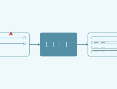
+----------------------------------------------------------------------+| UART DMA OVERRUN RECOVERY || STATE MACHINE (BARE METAL / LL) |+----------------------------------------------------------------------+| || NORMAL OPERATION || | || | Overrun Detected (ISR.ORE = 1 or SR.ORE = 1) || v || +-----------------+ || | DISABLE DMA RX | LL_USART_DisableDMAReq_RX() || | (CR3.DMAR=0) | || +--------+--------+ || | || | Flush stale data || v || +-----------------+ || | CLEAR ORE FLAG | Write 1 to ICR.ORECF (V2) or || | | Read SR then DR (V1) || +--------+--------+ || | || | Abort & Reinit DMA || v || +-----------------+ || | REINIT DMA | LL_DMA_DisableStream() || | (Stream/Channel)| [Wait for EN=0] -> Reconfig -> Enable || +--------+--------+ || | || | Re-enable DMA RX || v || +-----------------+ || | ENABLE DMA RX | LL_USART_EnableDMAReq_RX() || | (CR3.DMAR=1) | || +--------+--------+ || | || | SUCCESS || v || NORMAL OPERATION || |+----------------------------------------------------------------------+
UART DMA overrun on STM32 is a timing violation, not a software defect. The fix requires:
HAL_UART_ERROR_ORE in HAL or USART_ISR.ORE in LLThe circular DMA + IDLE line detection approach is the most robust for variable-length protocols. For fixed-packet protocols with RTS/CTS available, hardware flow control eliminates overrun entirely. Always monitor overrun counters in production — a non-zero count indicates a latent timing margin issue that will surface under load.
Quick Links
Legal Stuff