

Preventing ISR Stack Overflow in Embedded C
August 31, 2026
5 min
The Cortex-M Vector Table Offset Register (VTOR) is the single most overlooked register in embedded firmware startup sequences. A misconfigured VTOR doesn’t just break interrupts — it causes silent HardFaults, phantom resets, and debugging sessions that end in frustration. This article covers the alignment requirements, relocation mechanics, and the startup code patterns that prevent vector table bugs from shipping to production.
The Cortex-M vector table lives at address 0x00000000 at reset. This works for simple bare-metal applications where the flash image starts at 0x08000000 and the vector table is the first thing in the image. But real-world firmware introduces complications:
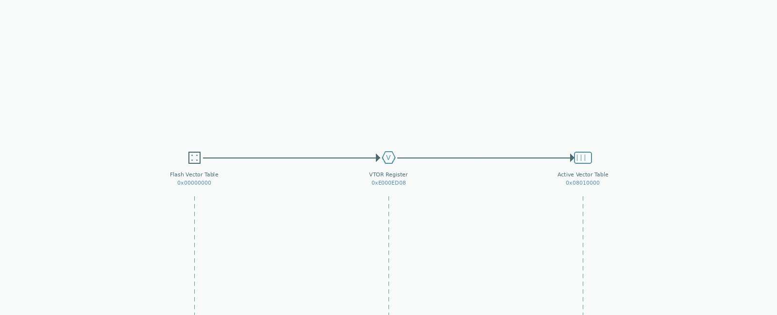
0x08010000) and need the vector table thereVTOR (0xE000ED08 in the System Control Block) tells the processor: “The vector table starts here, not at zero.” Writing it correctly is non-negotiable.
+------------------------------------------------------------------------------------+| Cortex-M Reset & VTOR Sequence |+====================================================================================+| || [POWER-ON RESET] || | || v || [HARDWARE FETCHES INITIAL SP FROM 0x00000000] || [HARDWARE FETCHES INITIAL PC FROM 0x00000004 (Reset_Handler)] || | || v || [RESET_HANDLER EXECUTES IN THREAD MODE, MSP ACTIVE] || | || v || [SYSTEM INIT: Clock config, Flash wait states, FPU enable] || | || v || [CRITICAL WINDOW: VTOR MUST BE WRITTEN HERE] || | || | SCB->VTOR = (uint32_t)&__Vectors; // Or bootloader-provided address || | __DSB(); __ISB(); // Ensure write completes before interrupts enabled || | || v || [ENABLE INTERRUPTS: __enable_irq() OR NVIC_EnableIRQ()] || | || v || [MAIN() / RTOS START] || |+------------------------------------------------------------------------------------+
The critical rule: VTOR must be written before any interrupt can fire. This means after clock initialization but before __enable_irq() or the first NVIC_EnableIRQ() call. The __DSB() / __ISB() barrier pair ensures the write is globally visible before the processor samples VTOR on the next exception entry.
| Core | Minimum Alignment Rule |
|---|---|
| Cortex-M0 | N/A (No VTOR, fixed at 0x00000000) |
| Cortex-M0+ | 128 bytes minimum (ARMv6-M), or next power of two of table size |
| Cortex-M3/M4 | 128 bytes minimum, or next power of two of total table size |
| Cortex-M7/M33/M55 | 128 bytes minimum (or 256+ depending on table size/cache line) |
The alignment rule: The vector table base address must be aligned to the size of the table rounded up to the next power of two. The VTOR register implementation masks lower address bits to enforce this — the exact number of masked bits depends on how many interrupts the device supports.
For example, an STM32F4 with 82 external interrupts and 16 system exceptions has 98 entries.
98 entries × 4 bytes = 392 bytes.
The next power of two is 512 bytes.
If the silicon masks VTOR bits [8:0] to enforce 512-byte alignment, writing a 256-byte-aligned address with bit 8 set (e.g., 0x08010100) would be silently truncated to 0x08010000 — pointing VTOR at the wrong memory.
Practical rule: Calculate your exact alignment based on (16 + IRQ_COUNT) * 4 and round up to the next power of two. For many modern MCUs, this means using a 512-byte (0x200) or 1024-byte (0x400) alignment in the linker script.
// Linker script snippet — force vector table alignmentSECTIONS{.isr_vector : ALIGN(512){. = ALIGN(512);KEEP(*(.isr_vector)). = ALIGN(512);} > FLASH}
// Startup code — verify alignment at runtimeextern uint32_t __Vectors[];extern uint32_t _estack;void Reset_Handler(void);__attribute__((section(".isr_vector")))const uint32_t *const g_pfnVectors[] = {(uint32_t *)&_estack, // Initial SP(uint32_t *)Reset_Handler, // Reset handler// ... other handlers};void SystemInit(void) {uint32_t vtor_addr = (uint32_t)g_pfnVectors;// Runtime alignment check (e.g., 512-byte alignment = 0x1FF mask)if (vtor_addr & 0x1FF) {// Alignment fault: trap here in debugwhile (1) { __BKPT(0); }}SCB->VTOR = vtor_addr;__DSB();__ISB();}
The most common VTOR bug in production: the bootloader sets VTOR for its vector table, then jumps to the application without restoring VTOR to the application’s vector table.
// Bootloader jump to application — CORRECT patterntypedef void (*app_entry_t)(void);void jump_to_application(uint32_t app_address) {// 1. Disable all interrupts FIRST__disable_irq();// 2. Clear pending NVIC interrupts// Warning: Writing to unimplemented ICER/ICPR registers may cause a BusFault!// Adjust the loop limit based on your MCU's specific IRQ count (e.g., 3 for 82 IRQs)for (int i = 0; i < 3; i++) {NVIC->ICER[i] = 0xFFFFFFFF;NVIC->ICPR[i] = 0xFFFFFFFF;}// 3. Restore VTOR to application's vector table// The application's vector table is at its load addressSCB->VTOR = app_address;__DSB();__ISB();// 4. Load application's initial SPuint32_t app_sp = *(volatile uint32_t *)app_address;__set_MSP(app_sp);// 5. Jump to application's Reset_Handler (second word in vector table)app_entry_t app_entry = (app_entry_t)*(volatile uint32_t *)(app_address + 4);app_entry();}
Common mistake: Forgetting step 3. The application starts with VTOR still pointing to the bootloader’s vector table. The first interrupt (usually SysTick) fetches the wrong handler address → HardFault → lockup → reset loop.
RTOSes and advanced firmware sometimes relocate the vector table to RAM to allow runtime handler patching (e.g., for software breakpoints, profiling, or hot-patching).
// RAM vector table relocation — typically done early in main()#define VECTOR_TABLE_SIZE (48 * 4) // 16 system + 32 external = 48 entries#define VECTOR_TABLE_ALIGN 256__attribute__((aligned(VECTOR_TABLE_ALIGN)))static uint32_t ram_vector_table[VECTOR_TABLE_SIZE / 4];void relocate_vector_table_to_ram(void) {// 1. Copy flash vector table to RAMextern uint32_t __Vectors[];memcpy(ram_vector_table, __Vectors, VECTOR_TABLE_SIZE);// 2. Point VTOR at RAM copySCB->VTOR = (uint32_t)ram_vector_table;__DSB();__ISB();// 3. Now you can modify handlers at runtime// ram_vector_table[EXTI0_IRQn + 16] = (uint32_t)my_custom_exti0_handler;}
Critical constraints for RAM vector tables:
Execute Never = 0, Read/Writerelocate_vector_table_to_ram() is called after the C runtime initializes .bss (which zeroes the array), so the memcpy overwrites the zeroed memory with valid vectorsWhen interrupts don’t fire or HardFaults happen immediately after enabling interrupts:
+------------------------------------------------------------------------------+| VTOR DEBUG CHECKLIST |+==============================================================================+| || [ ] 1. Read SCB->VTOR in debugger - does it match vector table addr? || [ ] 2. Is address aligned to power-of-two size? (e.g., addr & 0x1FF == 0) || [ ] 3. Is the memory region mapped as EXECUTABLE in MPU? || [ ] 4. Does the vector table contain valid handler addresses? || - Check entry 0 (Initial SP) points to valid stack top || - Check entry 1 (Reset_Handler) points to code in flash/RAM || - Check a few IRQ entries (e.g., SysTick at offset 15*4) || [ ] 5. Was VTOR written BEFORE __enable_irq() or first NVIC_EnableIRQ()? || [ ] 6. Are __DSB() / __ISB() barriers present after VTOR write? || [ ] 7. If bootloader exists: does it restore VTOR before jumping to app? || [ ] 8. Check HFSR (0xE000ED2C) after HardFault - FORCED bit set? || -> Indicates escalated fault, likely from bad vector fetch || |+------------------------------------------------------------------------------+
Pro tip: Add a runtime assertion in SystemInit() that reads back VTOR and compares it to the expected address. Catches linker script drift immediately.
void SystemInit(void) {SCB->VTOR = (uint32_t)&__Vectors;__DSB(); __ISB();// Verify VTOR write took effectassert(SCB->VTOR == (uint32_t)&__Vectors);}
| Anti-Pattern | Symptom | Fix |
|---|---|---|
| Writing VTOR after enabling interrupts | First interrupt (usually SysTick) HardFaults | Move VTOR write before __enable_irq() |
Forgetting __DSB() / __ISB() | Intermittent HardFaults under load | Add barriers after every VTOR write |
| Aligning to fixed 256 bytes on large MCUs | Upper IRQs trigger wrong handlers or HardFaults | Align to next power of two of (16 + IRQ_count) * 4 |
| Bootloader doesn’t restore VTOR | App works until first interrupt | Restore VTOR in bootloader jump sequence |
| Vector table in non-executable RAM | MemManage fault (IACCVIOL) / HardFault on IRQ | Configure MPU region as executable (XN=0) |
Using SCB->VTOR = 0 to “reset” | Processor uses default table at 0x0 (wrong image) | Write actual vector table address |
The Vector Table Offset Register is a single 32-bit register, but it controls the entry point for every exception in the system. The rules are simple:
__DSB(); __ISB(); after every writeSCB->VTOR == expected_address in SystemInit()Violate any of these, and the first interrupt becomes a HardFault with no handler to catch it. Follow them, and VTOR becomes a set-and-forget register that just works.
portable/GCC/ARM_CM3/port.c — vPortStartFirstTask() VTOR expectationsQuick Links
Legal Stuff