

Bitwise Modulo in C: Optimizing Embedded Systems
September 26, 2026
5 min
STM32 DMA double buffering is the standard pattern for continuous high-throughput data acquisition — ADC sampling, audio streaming, communication protocols. The concept is simple: two buffers, DMA fills one while CPU processes the other, swap on transfer complete. In practice, data corruption appears in three forms: torn reads (CPU reads half-old half-new data), stale data (CPU reads cached copy), and buffer overrun (DMA overwrites unprocessed buffer). Each stems from a specific hardware-software interaction that the reference manual mentions but doesn’t emphasize.
A common mistake is implementing double buffering manually by disabling the DMA stream in the Transfer Complete (TC) interrupt, swapping pointers in software, and re-enabling it. For continuous data acquisition like ADC sampling, this introduces a fatal gap: while the DMA is disabled, the peripheral continues generating data. The ADC data register is overwritten, and samples are permanently lost (ADC Overrun).
// WRONG: Manual pointer swap causes dropped ADC samplesvoid DMA1_Stream0_IRQHandler(void) {if (LL_DMA_IsActiveFlag_TC0(DMA1)) {LL_DMA_ClearFlag_TC0(DMA1);LL_DMA_DisableStream(DMA1, LL_DMA_STREAM_0);while (LL_DMA_IsEnabledStream(DMA1, LL_DMA_STREAM_0)); // ADC overrun happens here!active_buffer = (active_buffer == buffer_a) ? buffer_b : buffer_a;LL_DMA_SetMemoryAddress(DMA1, LL_DMA_STREAM_0, (uint32_t)active_buffer);LL_DMA_EnableStream(DMA1, LL_DMA_STREAM_0);}}
The true fix is to never swap pointers in software. Instead, use the STM32’s hardware Double Buffer Mode (DBM) or Circular Mode. These modes automatically wrap or swap memory targets at the hardware level with zero latency, entirely eliminating the race condition.
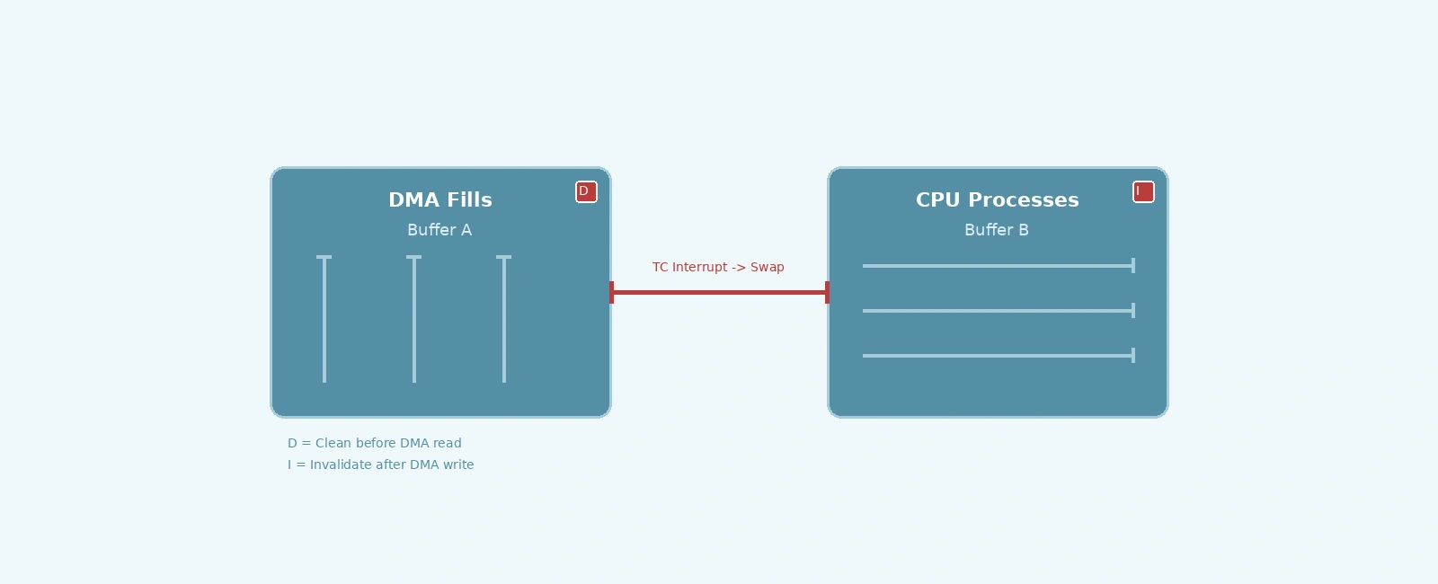
Cortex-M7 (STM32H7, STM32F7) has a data cache. DMA bypasses cache entirely — it reads/writes physical RAM. The CPU reads cached data. Without explicit cache maintenance, the CPU sees stale data after DMA writes, or DMA reads stale data after CPU writes.
// Before DMA reads from buffer (CPU wrote to it)// Second argument is size in bytesSCB_CleanDCache_by_Addr((uint32_t*)buffer, BUFFER_SIZE_BYTES);// After DMA writes to buffer (CPU will read it)// Second argument is size in bytesSCB_InvalidateDCache_by_Addr((uint32_t*)buffer, BUFFER_SIZE_BYTES);
For double buffering, the inactive buffer must be invalidated before CPU access. The active buffer must be cleaned before DMA starts if CPU modified it.
When using Circular Mode as a double buffer, the Half-Transfer (HT) interrupt is critical. It fires at the exact midpoint of the buffer. It signals “first half ready for processing” while the DMA continues filling the second half uninterrupted.
If you neglect the HT interrupt and only process data on the TC interrupt, you force the CPU to process the entire buffer before the DMA wraps around to the beginning. This doubles the effective latency budget requirement and severely risks data overrun if a processing spike occurs.
#include "stm32h7xx_hal.h"#define HALF_BUFFER_SIZE 1024#define FULL_BUFFER_SIZE (HALF_BUFFER_SIZE * 2)// 32-byte aligned for Cortex-M7 D-Cache linesstatic uint32_t dma_buffer[FULL_BUFFER_SIZE] __attribute__((section(".dma_buffer"), aligned(32)));static volatile uint8_t buffer_half_ready = 0; // 0 = none, 1 = first half, 2 = second halfstatic volatile uint32_t overrun_count = 0;void DMA1_Stream0_IRQHandler(void) {// Half-transfer: first half of the buffer is readyif (LL_DMA_IsActiveFlag_HT0(DMA1)) {LL_DMA_ClearFlag_HT0(DMA1);// Invalidate cache for the first half before CPU readSCB_InvalidateDCache_by_Addr((uint32_t*)&dma_buffer[0], HALF_BUFFER_SIZE * 4);buffer_half_ready = 1;}// Transfer complete: second half of the buffer is readyif (LL_DMA_IsActiveFlag_TC0(DMA1)) {LL_DMA_ClearFlag_TC0(DMA1);// Invalidate cache for the second half before CPU readSCB_InvalidateDCache_by_Addr((uint32_t*)&dma_buffer[HALF_BUFFER_SIZE], HALF_BUFFER_SIZE * 4);buffer_half_ready = 2;}// Transfer errorif (LL_DMA_IsActiveFlag_TE0(DMA1)) {LL_DMA_ClearFlag_TE0(DMA1);overrun_count++;}}int main(void) {HAL_Init();SystemClock_Config();// Enable D-cache for Cortex-M7SCB_EnableDCache();// DMA clock enableLL_AHB1_GRP1_EnableClock(LL_AHB1_GRP1_PERIPH_DMA1);// DMA stream configurationLL_DMA_SetChannelSelection(DMA1, LL_DMA_STREAM_0, LL_DMA_CHANNEL_0);LL_DMA_SetDataTransferDirection(DMA1, LL_DMA_STREAM_0, LL_DMA_DIRECTION_PERIPH_TO_MEMORY);LL_DMA_SetStreamPriorityLevel(DMA1, LL_DMA_STREAM_0, LL_DMA_PRIORITY_HIGH);LL_DMA_SetMode(DMA1, LL_DMA_STREAM_0, LL_DMA_MODE_CIRCULAR); // Crucial for continuous streaming!LL_DMA_SetPeriphIncMode(DMA1, LL_DMA_STREAM_0, LL_DMA_PERIPH_NOINCREMENT);LL_DMA_SetMemoryIncMode(DMA1, LL_DMA_STREAM_0, LL_DMA_MEMORY_INCREMENT);LL_DMA_SetPeriphSize(DMA1, LL_DMA_STREAM_0, LL_DMA_PDATAALIGN_WORD);LL_DMA_SetMemorySize(DMA1, LL_DMA_STREAM_0, LL_DMA_MDATAALIGN_WORD);LL_DMA_SetFIFOMode(DMA1, LL_DMA_STREAM_0, LL_DMA_FIFOMODE_ENABLE);LL_DMA_SetFIFOThreshold(DMA1, LL_DMA_STREAM_0, LL_DMA_FIFOTHRESHOLD_FULL);LL_DMA_SetMemoryBurst(DMA1, LL_DMA_STREAM_0, LL_DMA_MBURST_SINGLE);LL_DMA_SetPeriphBurst(DMA1, LL_DMA_STREAM_0, LL_DMA_PBURST_SINGLE);// Set addresses and sizeLL_DMA_SetPeriphAddress(DMA1, LL_DMA_STREAM_0, (uint32_t)&ADC1->DR);LL_DMA_SetMemoryAddress(DMA1, LL_DMA_STREAM_0, (uint32_t)&dma_buffer[0]);LL_DMA_SetDataLength(DMA1, LL_DMA_STREAM_0, FULL_BUFFER_SIZE);// Enable HT, TC, and TE interruptsLL_DMA_EnableIT_HT(DMA1, LL_DMA_STREAM_0);LL_DMA_EnableIT_TC(DMA1, LL_DMA_STREAM_0);LL_DMA_EnableIT_TE(DMA1, LL_DMA_STREAM_0);NVIC_SetPriority(DMA1_Stream0_IRQn, 5);NVIC_EnableIRQ(DMA1_Stream0_IRQn);// Start ADC + DMALL_DMA_EnableStream(DMA1, LL_DMA_STREAM_0);LL_ADC_REG_StartConversion(ADC1);while (1) {// Process ready buffersif (buffer_half_ready == 1) {process_adc_data(&dma_buffer[0], HALF_BUFFER_SIZE);buffer_half_ready = 0;} else if (buffer_half_ready == 2) {process_adc_data(&dma_buffer[HALF_BUFFER_SIZE], HALF_BUFFER_SIZE);buffer_half_ready = 0;}}}
Place the DMA buffer in a dedicated RAM section with explicit alignment to ensure the buffer starts on a cache line boundary:
/* In linker script */.dma_buffer (NOLOAD) :{. = ALIGN(32);*(.dma_buffer). = ALIGN(32);} > RAM_D2
32-byte alignment ensures the buffer starts on a cache line boundary (Cortex-M7 cache line = 32 bytes). Since HALF_BUFFER_SIZE * 4 = 4096 bytes is a multiple of 32, the boundary between the two buffer halves also falls on a cache line boundary. This prevents false sharing where invalidating one half’s cache lines affects the other.
Full DMA Transfer (2048 samples @ 1 MSPS) = 2.048 msHalf Transfer (1024 samples @ 1 MSPS) = 1.024 msCPU Processing Budget per half = 1.024 msCache Invalidate (1024 words = 4 KB) = ~15 µsTotal ISR Overhead (flag clear + invalidate) = ~18 µs
With HT + TC handling, the CPU gets 1.024 ms to process each 1024-sample half while the DMA fills the other half continuously. Without HT handling (TC only), the CPU would need to process all 2048 samples within 2.048 ms — but with zero margin for variability since the DMA immediately wraps around.
| Symptom | Root Cause | Fix |
|---|---|---|
| Periodic glitches at buffer boundary | Cache line shared between buffers | 32-byte alignment + separate cache lines |
| Missed samples / ADC Overrun | Software buffer swap via stream disable | Use Circular Mode with HT/TC interrupts |
| Random corruption under load | HT interrupt not handled, overrun | Implement HT processing or increase buffer size |
| Hard fault in ISR | Unaligned memory access | Ensure buffer alignment, use word-aligned pointers |
| Data stale after first transfer | D-cache not enabled or maintained | SCB_EnableDCache() + Clean/Invalidate protocol |
addr % 32 == 0 for both buffer halvesoverrun_count in productionSTM32 DMA double buffering corruption stems from three hardware realities: DMA and CPU share memory without hardware coherency (Cortex-M7), software buffer swapping creates fatal gaps (dropped ADC samples), and half-transfer handling is necessary for variable processing loads. The fix is disciplined cache maintenance, utilizing Hardware Circular Mode to continuously stream without disabling the DMA, and precise HT/TC interrupt utilization. The implementation above runs corruption-free at 1 MSPS ADC sampling on STM32H743.
stm32h7xx_hal_dma_ex.c - Double buffer mode implementationQuick Links
Legal Stuff