

Software UART for Embedded Debugging: GPIO-Based Serial
September 11, 2026
4 min
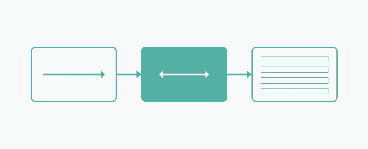
UART PERIPHERAL DMA CONTROLLER MEMORY BUFFER┌─────────────────────┐ ┌─────────────────────┐ ┌─────────────────────┐│ RDR (Receive │ │ Channel Config: │ │ Circular Buffer ││ Data Register) │──▶│ Periph→Memory │──▶│ [byte][byte][byte] ││ │ │ Circular Mode │ │ [byte][byte][byte] ││ OVRE Flag │ │ Transfer Complete │ │ [byte][byte][byte] ││ (Overrun Error) │ │ Half-Transfer IRQ │ │ [byte][byte][byte] │└─────────────────────┘ └─────────────────────┘ └─────────────────────┘│ │ ││ Byte arrives │ Auto-transfer │ CPU reads at│ every 86.8µs @ │ without CPU │ own pace via│ 115200 baud │ intervention │ half/full IRQs▼ ▼ ▼┌─────────┐ ┌─────────────┐ ┌─────────────┐│ OVRE │ │ Zero CPU │ │ Deterministic││ Risk! │ ───▶ │ Overhead │ ───▶ │ Processing │└─────────┘ └─────────────┘ └─────────────┘
UART overrun errors are a common issue in embedded serial communication, particularly when handling high-speed data streams. These errors occur when the microcontroller’s UART peripheral receives new data before the CPU has read the previously received data, leading to data loss and potential system instability. In STM32 microcontrollers, this problem can be effectively resolved by leveraging the Direct Memory Access (DMA) controller to automate data transfer, thereby eliminating the need for CPU intervention during reception.
At 115200 baud, a byte arrives every ~87 µs. The CPU must read the RDR within this window—impossible under load. DMA removes this timing constraint entirely.
The UART overrun error (OVRE flag) is set when the UART’s receive data register (RDR) is not read before the next byte arrives. In a polling-based or interrupt-driven reception scheme, the CPU must service the UART interrupt or poll the status register within the time it takes to receive a single byte. At high baud rates, this window becomes extremely narrow, increasing the likelihood of overruns especially when the CPU is busy with other tasks.
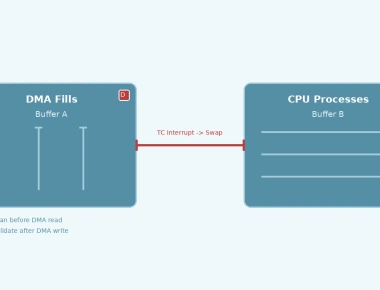
The DMA controller provides a hardware-assisted mechanism for transferring data between peripherals and memory without CPU involvement. By configuring the DMA to handle UART reception, the received bytes are automatically moved from the UART’s RDR to a memory buffer, freeing the CPU to handle other tasks or simply reducing its workload.
| Approach | CPU Involvement | Max Sustainable Rate | OVRE Risk |
|---|---|---|---|
| Polling | 100% | Low | High |
| Interrupt | Per byte | Medium | Medium |
| DMA Circular | Per buffer | Very High | Zero |
Activate the clock for the desired UART peripheral and the DMA controller.
Set the UART’s DMA request enable bit for reception (DMAR) in the control register 3 (CR3).
Enable the DMA channel to begin transferring data.
In the DMA interrupt service routine (ISR), process the received data from the buffer based on whether the transfer complete or half-transfer flag is set.
Below is a complete example demonstrating DMA-based UART reception on an STM32F4xx using the HAL library. The code configures USART2 at 115200 baud with a circular DMA buffer of 64 bytes.
#include "stm32f4xx_hal.h"UART_HandleTypeDef huart2;DMA_HandleTypeDef hdma_usart2_rx;uint8_t rx_buffer[64];void SystemClock_Config(void);static void MX_GPIO_Init(void);static void MX_DMA_Init(void);static void MX_USART2_UART_Init(void);int main(void){HAL_Init();SystemClock_Config();MX_GPIO_Init();MX_DMA_Init();MX_USART2_UART_Init();// Start DMA reception in circular modeif (HAL_UART_Receive_DMA(&huart2, rx_buffer, sizeof(rx_buffer)) != HAL_OK) {Error_Handler();}while (1) {// Main loop - CPU is free for other tasks// Process rx_buffer in DMA ISR or via flags}}void SystemClock_Config(void){// Clock configuration specific to your STM32}static void MX_GPIO_Init(void){// GPIO initialization for UART pins (PA2: TX, PA3: RX)__HAL_RCC_GPIOA_CLK_ENABLE();GPIO_InitTypeDef GPIO_InitStruct = {0};GPIO_InitStruct.Pin = GPIO_PIN_2|GPIO_PIN_3;GPIO_InitStruct.Mode = GPIO_MODE_AF_PP;GPIO_InitStruct.Pull = GPIO_NOPULL;GPIO_InitStruct.Speed = GPIO_SPEED_FREQ_VERY_HIGH;GPIO_InitStruct.Alternate = GPIO_AF7_USART2;HAL_GPIO_Init(GPIOA, &GPIO_InitStruct);}static void MX_DMA_Init(void){__HAL_RCC_DMA1_CLK_ENABLE();hdma_usart2_rx.Instance = DMA1_Stream5;hdma_usart2_rx.Init.Channel = DMA_CHANNEL_4;hdma_usart2_rx.Init.Direction = DMA_PERIPH_TO_MEMORY;hdma_usart2_rx.Init.PeriphInc = DMA_PINC_DISABLE;hdma_usart2_rx.Init.MemInc = DMA_MINC_ENABLE;hdma_usart2_rx.Init.PeriphDataAlignment = DMA_PDATAALIGN_BYTE;hdma_usart2_rx.Init.MemDataAlignment = DMA_MDATAALIGN_BYTE;hdma_usart2_rx.Init.Mode = DMA_CIRCULAR;hdma_usart2_rx.Init.Priority = DMA_PRIORITY_LOW;hdma_usart2_rx.Init.FIFOMode = DMA_FIFOMODE_DISABLE;if (HAL_DMA_Init(&hdma_usart2_rx) != HAL_OK) {Error_Handler();}__HAL_LINKDMA(&huart2, hdmarx, hdma_usart2_rx);// DMA interrupt initHAL_NVIC_SetPriority(DMA1_Stream5_IRQn, 0, 0);HAL_NVIC_EnableIRQ(DMA1_Stream5_IRQn);}static void MX_USART2_UART_Init(void){__HAL_RCC_USART2_CLK_ENABLE();huart2.Instance = USART2;huart2.Init.BaudRate = 115200;huart2.Init.WordLength = UART_WORDLENGTH_8B;huart2.Init.StopBits = UART_STOPBITS_1;huart2.Init.Parity = UART_PARITY_NONE;huart2.Init.Mode = UART_MODE_TX_RX;huart2.Init.HwFlowCtl = UART_HWCONTROL_NONE;huart2.Init.OverSampling = UART_OVERSAMPLING_16;if (HAL_UART_Init(&huart2) != HAL_OK) {Error_Handler();}// Enable DMA for UART receptionSET_BIT(huart2.Instance->CR3, USART_CR3_DMAR);}void DMA1_Stream5_IRQHandler(void){HAL_DMA_IRQHandler(&huart2.hdmarx);}void HAL_UART_RxCpltCallback(UART_HandleTypeDef *huart){if (huart->Instance == USART2) {// Handle full buffer reception// Process rx_buffer[0] to rx_buffer[63]}}void HAL_UART_RxHalfCpltCallback(UART_HandleTypeDef *huart){if (huart->Instance == USART2) {// Handle half-buffer reception// Process rx_buffer[0] to rx_buffer[31]}}
// Buffer must accommodate worst-case ISR latency// At 115200 baud: 1 byte/87µs// If max ISR latency = 500µs → need 6+ bytes headroom// 64-byte buffer = 5.5ms headroom (comfortable)#define RX_BUFFER_SIZE 64
// DMA IRQ priority must be >= UART IRQ priority// to prevent DMA ISR being preemptedHAL_NVIC_SetPriority(DMA1_Stream5_IRQn, 5, 0); // Example
void HAL_UART_ErrorCallback(UART_HandleTypeDef *huart) {if (huart->Instance == USART2) {uint32_t error = HAL_UART_GetError(huart);if (error & HAL_UART_ERROR_ORE) {// Overrun still possible if DMA stops!// Clear flag and restart DMA__HAL_UART_CLEAR_OREFLAG(huart);HAL_UART_Receive_DMA(huart, rx_buffer, RX_BUFFER_SIZE);}}}
// Monitor OVRE flag in real-timewhile (1) {if (__HAL_UART_GET_FLAG(&huart2, UART_FLAG_ORE)) {// Overrun occurred - should never happen with DMAGPIO_WritePin(LED_PORT, LED_PIN, GPIO_PIN_SET); // Visual alert__HAL_UART_CLEAR_OREFLAG(&huart2);}}
HAL_UART_RxHalfCpltCallback and HAL_UART_RxCpltCallbackUART overrun errors in STM32 can be effectively mitigated by utilizing the DMA controller for automatic data transfer. This approach eliminates the CPU’s strict timing constraints for reading the UART’s receive data register, thereby preventing data loss and improving system reliability. The provided code example demonstrates a complete implementation using the STM32 HAL library, enabling developers to integrate DMA-based UART reception into their applications with minimal effort.
Quick Links
Legal Stuff