

Bitwise Modulo in C: Optimizing Embedded Systems
September 26, 2026
5 min
In virtually every embedded system, interrupt service routines (ISRs) need to pass data to the background main loop or to an RTOS task. The UART receive interrupt collects bytes and hands them off. A timer ISR samples a sensor reading for later processing. A DMA complete interrupt signals that a block of data is ready. The fundamental challenge is the same: how do you safely share data between an asynchronous interrupt handler and synchronous application code without corrupting state?
The obvious answer—disable interrupts around shared data access—works, but it introduces jitter into your interrupt response and scales poorly as system complexity grows. A more elegant solution is the single-producer single-consumer (SPSC) lock-free ring buffer, a data structure that requires no mutexes, no critical sections, and no interrupt disabling. The only hidden ingredient is correct use of memory barriers—and getting them right is where most embedded developers stumble.
This article walks through the complete design and implementation of a lock-free SPSC ring buffer for ISR-to-task communication on ARM Cortex-M processors, explains when and why memory barriers are needed, and identifies the most common pitfalls that cause silent data corruption in production firmware.
Consider a typical UART receive driver. The UART RX interrupt fires every time a byte arrives. The ISR must store the byte somewhere so the main loop can process it later. The naive approach wraps the buffer access in a critical section:
// Naive: disabling interrupts around shared datavoid UART4_IRQHandler(void) {uint8_t byte = UART4->RXDR;__disable_irq(); // CRITICAL SECTION STARTrx_buffer[head] = byte;head = (head + 1) & MASK;__enable_irq(); // CRITICAL SECTION END}
This works, but every byte received adds interrupt latency for the entire system. If your UART runs at 1 Mbps (one byte every 8 µs), the processor spends a meaningful fraction of its time with interrupts disabled. Worse, if the main loop also disables interrupts for other purposes, you create nested critical sections with unpredictable worst-case latency.
A lock-free ring buffer eliminates this entirely. The ISR never disables interrupts. The main loop never disables interrupts. The two contexts coordinate through a carefully designed protocol typically requiring one barrier on the producer side.
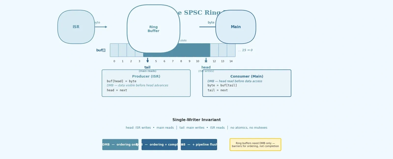
The ring buffer uses a fixed-size array and two indices: head (written only by the producer) and tail (written only by the consumer). The key insight is that with only one writer per index, no read-modify-write protocol is needed for the indices themselves—each context has exclusive ownership of its index.
The invariant that makes this work:
buf[head], then advances head.buf[tail], then advances tail.Because there is no concurrent writer for any single variable, we do not need atomic compare-and-swap operations or hardware locks. The only requirement is that the memory access order visible to the other context matches the program order.
While many Cortex-M systems behave as strongly ordered for normal memory, write buffers, caches (e.g., Cortex-M7), and bus interactions can still affect memory visibility ordering. This means the hardware and compiler may reorder memory accesses for performance. Consider the producer’s code:
buf[head] = byte; // Store the data bytehead = next_head; // Publish by advancing head
Without a barrier, the processor could reorder these stores—publishing the new head value before the data byte is actually written to memory. The consumer sees head advance, reads buf[old_head], and gets stale or zero data. This is not a theoretical concern; it happens in practice on Cortex-M7 and any processor with a write buffer or store forwarding.
The fix is a Data Memory Barrier (__DMB()), a CMSIS intrinsic that compiles to the ARM DMB instruction:
rb->buf[head] = byte; // Store the data byte__DMB(); // Barrier: ensure store completes before next storerb->head = next_head; // Publish: consumer can now see the new byte
The DMB instruction guarantees that all explicit memory accesses before the barrier are observed before any explicit memory accesses after the barrier. It does not stall the pipeline until writes reach external memory—it only enforces ordering, making it far cheaper than a DSB (Data Synchronization Barrier).
Here is a production-quality SPSC ring buffer implementation for a UART receive path on ARM Cortex-M:
#include <stdint.h>#include <stdbool.h>// CMSIS intrinsics provide __DMB, __DSB, __ISB on Cortex-M// For non-ARM targets, use compiler barriers or stdatomic#if defined(__ARM_ARCH)#include "cmsis_gcc.h" // or cmsis_armcc.h / cmsis_compiler.h"#else#define __DMB() __asm volatile("" ::: "memory")#endif#define RING_BUF_SIZE 256U /* Must be power of 2 */#define RING_BUF_MASK (RING_BUF_SIZE - 1U)typedef struct {uint8_t buf[RING_BUF_SIZE];volatile uint32_t head; /* Written by producer (ISR) only */volatile uint32_t tail; /* Written by consumer (main) only */} RingBuf_t;/*** Write one byte to the ring buffer (producer side).* Called from ISR context. Never disables interrupts.* Returns true on success, false if buffer is full.*/bool ring_buf_write(RingBuf_t *rb, uint8_t byte) {uint32_t head = rb->head;uint32_t next = (head + 1U) & RING_BUF_MASK;/* Full check: next == tail means no room (usable capacity is SIZE-1) */if (next == rb->tail) {return false;}rb->buf[head] = byte; /* Store data */__DMB(); /* Ensure data is visible before head advances */rb->head = next; /* Publish */return true;}/*** Read one byte from the ring buffer (consumer side).* Called from main loop context.* Returns true on success, false if buffer is empty.*/bool ring_buf_read(RingBuf_t *rb, uint8_t *out) {uint32_t tail = rb->tail;/* Empty check: tail == head means nothing to read */if (tail == rb->head) {return false;}__DMB(); /* Ensure head read completes before buf access */*out = rb->buf[tail]; /* Read data */__DMB(); /* Ensure data read completes before tail advances */rb->tail = (tail + 1U) & RING_BUF_MASK;return true;}/* ---- UART RX ISR ---- */static RingBuf_t g_uart_rx = { .head = 0, .tail = 0 };void UART4_IRQHandler(void) {uint8_t byte = (uint8_t)(UART4->RXDR & 0xFFU);ring_buf_write(&g_uart_rx, byte);UART4->ICR = USART_ICR_RXNECF; /* Clear overrun flag if needed */}/* ---- Main loop ---- */int main(void) {system_init();uart_init();for (;;) {uint8_t byte;while (ring_buf_read(&g_uart_rx, &byte)) {process_received_byte(byte);}enter_low_power_mode();}}
ARM provides three barrier instructions, and using the wrong one can cause subtle bugs or unnecessary performance overhead:
| Barrier | Guarantees | Use Case |
|---|---|---|
| DMB (Data Memory Barrier) | Ordering of explicit memory accesses | Lock-free data structures, producer-consumer protocols |
| DSB (Data Synchronization Barrier) | DMB + completion of all prior memory accesses | Before WFI/WFE, before sleep, after configuring MPU |
| ISB (Instruction Synchronization Barrier) | DSB + flush pipeline, refetch all subsequent instructions | After modifying vector tables, after self-modifying code, after MPU updates |
Rule of thumb: Use DMB for lock-free ring buffers. Use DSB before entering low-power sleep modes to ensure all writes reach the memory system. Use ISB only when changing the instruction execution context itself.
The consumer-side DMB in ring_buf_read is a conservative safety measure. It ensures the load of rb->head is completed before the load of rb->buf[tail]. Without it, the architecture does not guarantee ordering between independent loads, so buf[tail] could be read before the latest head value is fully observed. On simpler Cortex-M systems it is often not strictly required, but improves portability and safety.
A common misconception is that declaring shared variables as volatile is sufficient for ISR safety. volatile prevents the compiler from caching a register across sequence points and ensures each access generates a load/store instruction. However, volatile does not prevent the hardware from reordering memory accesses.
volatile uint32_t head; // Compiler won't optimize away loads/stores,// BUT the CPU may still reorder them!
Always combine volatile with appropriate memory barriers. volatile handles the compiler; barriers handle the hardware.
The lock-free pattern described here is safe only when there is exactly one writer per index variable. If you have:
DMB barriers—no atomics needed.For MPMC (multiple producer, multiple consumer) scenarios, ARMv8-A provides LSE atomic instructions (LDADD, LDEOR, etc.) that offer better scalability than exclusive monitor-based loops.
Lock-free algorithms are notoriously difficult to test because failures are timing-dependent. Strategies that help:
-O2 or higher, where the compiler reorders and optimizes aggressively.DSB before WFI: If your main loop enters sleep after draining the buffer, add a DSB before the WFI instruction to ensure all memory writes are visible before the processor suspends execution.The lock-free SPSC ring buffer is one of the most useful patterns in embedded systems programming. It decouples interrupt processing from application logic with zero interrupt latency overhead and zero risk of deadlock. The implementation is small—under 30 lines of C—but it depends on a correct understanding of memory ordering on modern processors.
The key takeaways: declare shared indices as volatile to prevent compiler reordering, insert __DMB() barriers to prevent hardware reordering, enforce single-writer ownership of each index variable, and resist the temptation to add more synchronization than the pattern requires. When applied correctly, this technique scales to any number of producer-consumer pairs in your firmware, from UART drivers to DMA completion handlers to custom event queues.
Quick Links
Legal Stuff