


DMA Programming in Embedded C for High-Throughput Data Transfer
June 12, 2026
3 min
Setting or clearing a single GPIO pin seems trivial until an interrupt service routine (ISR) needs to toggle the same pin from a different context. The classic read-modify-write sequence — load the port register, OR or AND with a mask, store back — is inherently non-atomic. If an ISR fires between the load and the store, its modification is silently lost when the main loop writes the stale value back. On ARM Cortex-M processors, the bit-band region solves this problem in hardware.
Consider the standard approach to setting pin 5 of GPIOA on an STM32:
// NON-ATOMIC: vulnerable to race conditionsGPIOA->ODR |= (1 << 5); // Set pin 5
This compiles to three instructions: load the ODR register, OR with the mask, store the result back. If an ISR modifies a different bit in the same ODR register between the load and the store, the ISR’s change is overwritten. The typical workaround is to disable interrupts around the operation, but that adds latency and complexity.
// Safe but costly: disables all interrupts__disable_irq();GPIOA->ODR |= (1 << 5);__enable_irq();
For a single bit write, disabling all interrupts is overkill. Bit-banding provides a better solution.
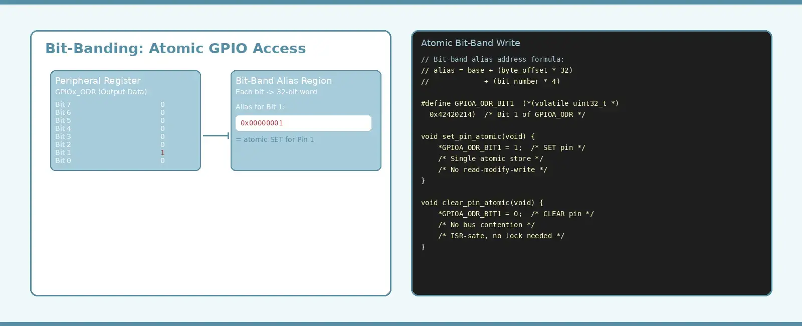
ARM Cortex-M3, M4, M7, and M33 cores map two peripheral and SRAM regions to alias regions where each bit of the original region is expanded into a full 32-bit word. Writing 1 to that word sets the corresponding bit in the original region; writing 0 clears it. The operation is atomic at the bus level — no read-modify-write, no race conditions.
The alias address is computed with a simple formula:
alias_addr = bit_band_base + (byte_offset_from_region * 32) + (bit_number * 4)
For the STM32F4 GPIOA ODR register at 0x40020014, the bit-band base for the peripheral region is 0x42000000. To access bit 1 of GPIOA ODR:
byte_offset = 0x40020014 - 0x40000000 = 0x20014bit_number = 1alias_addr = 0x42000000 + (0x20014 * 32) + (1 * 4)= 0x42000000 + 0x400280 + 0x4= 0x42420214
Bit-Band Alias Address Computation+-------------------------+ +-------------------------+| Peripheral Region | | Bit-Band Alias Region || Base: 0x40000000 | | Base: 0x42000000 || | | || GPIOA_ODR @ 0x40020014 | | Each bit -> 32-bit word || | | || bit 7 | bit 6 | ... | | WORD | WORD | ... || bit 1 | bit 0 | | for b7 | for b0 || | | |+-------------------------+ +-------------------------+| || alias = base + (offset * 32) || + (bit_num * 4) |+---------------------------------> 0x42420214
The cleanest approach is to define macros that compute the alias addresses at compile time:
// Bit-band alias macros for STM32 Cortex-M// Works on Cortex-M3, M4, M7, M33 (ARMv7-M / ARMv8-M)#define PERIPH_BITBAND_ADDR(addr, bit) \(((uint32_t)(addr) - 0x40000000) * 32 + (bit) * 4 + 0x42000000)#define SRAM_BITBAND_ADDR(addr, bit) \(((uint32_t)(addr) - 0x20000000) * 32 + (bit) * 4 + 0x22000000)// Convenience: define a single bit-band alias#define BITBAND_PERIPH(addr, bit) \(*(volatile uint32_t *)PERIPH_BITBAND_ADDR((uint32_t)addr, bit))// Usage: atomic GPIO pin control on STM32F4#define GPIOA_PIN1 BITBAND_PERIPH(&GPIOA->ODR, 1)#define GPIOA_PIN5 BITBAND_PERIPH(&GPIOA->ODR, 5)#define GPIOB_PIN12 BITBAND_PERIPH(&GPIOB->ODR, 12)
With these macros, setting or clearing a pin is a single atomic store instruction:
void gpio_init(void) {/* Enable GPIOA clock */RCC->AHB1ENR |= RCC_AHB1ENR_GPIOAEN;/* Configure PA1 as push-pull output, high speed */GPIOA->MODER &= ~(3U << (1 * 2)); /* Clear mode bits */GPIOA->MODER |= (1U << (1 * 2)); /* Set output mode */GPIOA->OSPEEDR |= (3U << (1 * 2)); /* High speed */}int main(void) {gpio_init();while (1) {GPIOA_PIN1 = 1; /* Atomic SET — single STR instruction */delay_ms(500);GPIOA_PIN1 = 0; /* Atomic CLEAR — single STR instruction */delay_ms(500);}}
The compiler generates a single STR instruction for each write — no read, no modify, no race window.
Bit-banding shines in scenarios where multiple contexts share GPIO pins or where timing precision is critical.
ISR-safe signaling. A timer ISR toggles a pin for a logic analyzer trigger while the main loop drives the same port for status LEDs. Without bit-banding, the main loop’s read-modify-write could corrupt the ISR’s pin state. With bit-banding, each context writes only its own bit — no interference.
Deterministic timing. Disabling interrupts adds jitter to the system response. Bit-banding eliminates the need for interrupt masking in single-bit GPIO operations, keeping interrupt latency predictable.
Multi-pin protocols. Bit-banging a communication protocol (like a software I2C or SPI master) requires precise timing on individual pins. Bit-banding ensures each pin transition is atomic and has deterministic cycle count.
// Bit-Band GPIO for Software SPI Master+-----------+ +-----------+| MCU | | Sensor || | | || PA5 (SCK)|------------------------->| SCK || PA6 (MOSI)|------------------------>| DI || PA7 (MISO)|<------------------------| DO || PA4 (CS) |------------------------->| CS |+-----------+ +-----------+// Bit-band aliases for software SPI#define SPI_SCK BITBAND_PERIPH(&GPIOA->ODR, 5)#define SPI_MOSI BITBAND_PERIPH(&GPIOA->ODR, 6)#define SPI_CS BITBAND_PERIPH(&GPIOA->ODR, 4)#define SPI_MISO BITBAND_PERIPH(&GPIOA->IDR, 7)uint8_t spi_transfer(uint8_t tx_byte) {uint8_t rx_byte = 0;for (int i = 7; i >= 0; i--) {/* Set MOSI based on current bit */SPI_MOSI = (tx_byte >> i) & 1;/* Clock high */SPI_SCK = 1;/* Read MISO */rx_byte |= (SPI_MISO & 1) << i;/* Clock low */SPI_SCK = 0;}return rx_byte;}
On a Cortex-M4, a bit-band store compiles to a single STR instruction — 2 clock cycles. Compare this to the read-modify-write approach:
| Operation | Instructions | Cycles (Cortex-M4) | Atomic |
|---|---|---|---|
GPIOA->ODR \|= (1 << 5) | LDR, ORR, STR | 6 | No |
GPIOA_PIN5 = 1 (bit-band) | STR | 2 | Yes |
__disable_irq() + RMW + __enable_irq() | CPSID, LDR, ORR, STR, CPSIE | 10+ | Yes |
The bit-band approach is both faster and atomic — a rare combination where correctness and performance align.
Architecture-specific. Bit-banding is available only on ARM Cortex-M3, M4, M7, M33, and M33F cores. Cortex-M0 and M0+ do not implement it. Always check the device’s Technical Reference Manual for bit-band region addresses.
Peripheral and SRAM only. The bit-band regions cover 0x40000000–0x400FFFFF (peripheral) and 0x20000000–0x200FFFFF (SRAM) on most STM32 devices. Registers outside these ranges cannot use bit-banding.
Single-bit only. Bit-banding operates on individual bits. If you need to write multiple bits atomically, consider using the BSRR (Bit Set/Reset Register) available on STM32 GPIO peripherals, which provides atomic set and reset of multiple bits in a single write.
// BSRR: atomic multi-bit set/reset (alternative to bit-band)// Upper 16 bits = reset, lower 16 bits = setGPIOA->BSRR = (1 << 5) | (1 << 12); // Set pins 5 and 12GPIOA->BSRR = (1 << 21) | (1 << 28); // Reset pins 5 and 12
Bit-banding is a hardware feature of ARM Cortex-M processors that maps individual bits to 32-bit alias addresses, enabling atomic single-bit writes without read-modify-write sequences or interrupt masking. The technique is invaluable for ISR-safe GPIO manipulation, deterministic pin timing, and software-implemented communication protocols. By defining clean macros for alias addresses, embedded C code gains both correctness and performance — a combination that is hard to achieve with software workarounds alone.
ARM Limited, “Cortex-M4 Technical Reference Manual,” Revision r0p1, Section 4: Memory Model — Bit-Banding, 2010. [Online]. Available: https://developer.arm.com/documentation/ddi0439/b/
ARM Limited, “ARMv7-M Architecture Reference Manual,” Section B3.2: Bit-banding, 2016. [Online]. Available: https://developer.arm.com/documentation/ddi0403/latest/
STMicroelectronics, “PM0214: STM32F4/F7/L4 Programming Manual,” Section 2.2.5: Bit-banding, Rev. 10, 2020.
Joseph Yiu, The Definitive Guide to ARM Cortex-M3 and Cortex-M4 Processors, 3rd ed. Newnes, 2014, Chapter 2: Memory Model — Bit-Band Operations.
Quick Links
Legal Stuff