


Understanding const and volatile Pointer Types in Embedded C
June 29, 2026
2 min
When developing firmware for microcontrollers, understanding how your code and data are placed in memory is crucial for creating reliable embedded systems. The linker script is the bridge between your C/C++ source code and the physical memory layout of the target hardware.
In embedded systems, you don’t have the luxury of an operating system managing memory layout for you. You must explicitly define where your program’s sections (.text, .data, .bss, stack, heap) reside in the available memory resources (Flash, RAM, etc.). A well-designed linker script ensures:
The foundation of any linker script is the MEMORY command, which defines the available memory resources on your microcontroller:
MEMORY{/* Flash memory for code and read-only data */FLASH (rx) : ORIGIN = 0x08000000, LENGTH = 512K/* SRAM for initialized/uninitialized variables, stack, heap */RAM (rwx) : ORIGIN = 0x20000000, LENGTH = 128K/* Optional: External memory regions */EXTMEM (rwx): ORIGIN = 0x60000000, LENGTH = 32M}
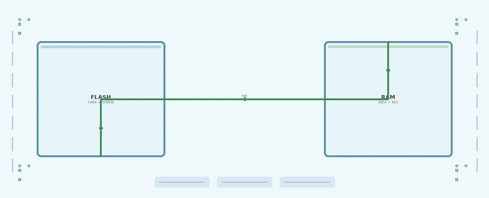
Memory Layout Diagram
Flash Memory (0x08000000 - 0x0807FFFF)+----------------+ 0x08000000| Vector Table |+----------------+| .text | (Code + .rodata)+----------------+| .ARM.exidx | (Exception index)+----------------+| .data (load) | <-- LMA (Load Memory Address) of .data+----------------+RAM (0x20000000 - 0x2001FFFF)+----------------+ 0x20000000| .data (run) | <-- Copied from Flash at startup (VMA)+----------------+| .bss | <-- Zero-initialized at startup+----------------+| Heap | --> Grows upwards+----------------+| ... | (Free space)+----------------+| Stack | <-- Grows downwards+----------------+ 0x20020000 (_estack / Initial SP)
The syntax is: NAME (attributes) : ORIGIN = address, LENGTH = size
Attributes:
r: readablew: writable x: executablea: allocatablei: initializedl: same as i!: negates preceding attributesAfter defining memory regions, you tell the linker where to place each section from your object files:
/* Minimum sizes for heap and stack — override these from the build system if needed */_Min_Heap_Size = 0x00000200; /* 512 bytes */_Min_Stack_Size = 0x00000800; /* 2 KB *//* Highest address of the user mode stack */_estack = ORIGIN(RAM) + LENGTH(RAM); /* one past last byte of RAM */SECTIONS{/* Vector table must be at the very start of Flash */.isr_vector :{KEEP(*(.isr_vector)). = ALIGN(4);} > FLASH/* Main program code and read-only constants */.text :{. = ALIGN(4);*(.text*) /* All code sections */*(.glue_7) /* ARM-to-Thumb interworking glue */*(.glue_7t) /* Thumb-to-ARM interworking glue */*(.eh_frame) /* Exception handling frames */*(.rodata*) /* Read-only data */KEEP (*(.init))KEEP (*(.fini)). = ALIGN(4);_etext = .; /* End of .text section */} > FLASH/* Exception handling index (for C++ or stack unwinding) */.ARM.exidx :{__exidx_start = .;*(.ARM.exidx*)__exidx_end = .;. = ALIGN(4);} > FLASH/* Used by the startup to initialize data */_sidata = LOADADDR(.data);/* Initialized data: stored in Flash, runtime copy to RAM */.data :{. = ALIGN(4);_sdata = .; /* Start address for initialization */*(.data*) /* All initialized data */. = ALIGN(4);_edata = .; /* End address */} > RAM AT> FLASH/* Uninitialized data: zeroed at startup */.bss :{. = ALIGN(4);_sbss = .; /* Start of .bss */__bss_start__ = _sbss;*(.bss*) /* All uninitialized data */*(COMMON) /* Common symbols */. = ALIGN(4);_ebss = .; /* End of .bss */__bss_end__ = _ebss;} > RAM/* Verify enough RAM remains for heap and stack */._user_heap_stack :{. = ALIGN(8);PROVIDE ( end = . );PROVIDE ( _end = . );. = . + _Min_Heap_Size;. = . + _Min_Stack_Size;. = ALIGN(8);} > RAM}
Common linker-related problems and their solutions:
Problem: “Section .text will not fit in region FLASH”
Solution:
arm-none-eabi-size command -Os for size)Problem: Variables not initialized correctly
Solution:
AT> or AT() directive pointing to the Flash location _sidata symbol is correctly definedProblem: Hard fault after startup
Solution:
Linker scripts are a fundamental but often overlooked aspect of embedded development. Mastering them gives you precise control over your system’s memory layout, leading to more reliable and efficient firmware. While the syntax may seem cryptic at first, understanding the MEMORY and SECTIONS commands unlocks the ability to tailor your embedded system’s memory map to exactly match your hardware and application requirements.
Take time to study your microcontroller’s reference manual, experiment with different memory placements, and always verify results with the linker map file. Your future self (and anyone maintaining your code) will thank you for the clarity and precision a well-crafted linker script provides.
Quick Links
Legal Stuff