Fixing SPI Clock Phase Polarity Mismatch in Multi-Slave
October 11, 2026
5 min
When you need to move data fast between a microcontroller and a peripheral—flash memory, SD cards, display controllers, ADCs, or high-performance sensors—SPI delivers the speed that UART and I²C simply cannot match. The Serial Peripheral Interface commonly operates in the 1–50 MHz range, depending on the device, with some high performance systems exceeding 100 MHz.
Despite its popularity, SPI trips up many engineers. There is no formal standard governing all SPI implementations, clock polarity and phase must be matched exactly between master and slave, and managing multiple chip-select lines adds hardware complexity. This article breaks down how SPI works, covers the four clock modes that cause the most configuration errors, and provides practical driver-level code you can adapt for your next project.
SPI uses a master-slave architecture connected by four signal lines. MOSI (Master Out, Slave In) carries data from master to slave. MISO (Master In, Slave Out) carries data from slave to master. SCLK is the serial clock generated exclusively by the master. CS/SS (Chip Select / Slave Select) is active low—the master pulls a specific slave’s CS pin low to begin communication.
All slaves share SCLK, MOSI, and MISO. Each slave gets its own dedicated CS line. This is a key difference from I²C: there are no bus addresses. Slave selection is entirely hardware-based through GPIO pins.
SPI is inherently full-duplex. Both master and slave contain a shift register. On each clock edge, one bit shifts out from the master onto MOSI while one bit shifts in from MISO. After eight clock cycles, the devices have exchanged one complete byte.
Every transmission is simultaneously a reception. To read from a slave, the master sends a dummy byte (0xFF) to generate the clock cycles that cause the slave to shift out its data.
uint8_t spi_exchange(uint8_t tx_data) {SPI0.DATA = tx_data;while (!(SPI0.INTFLAGS & SPI_IF_bm));return SPI0.DATA;}
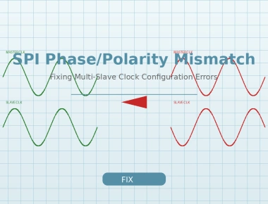
Clock polarity (CPOL) and clock phase (CPHA) define four valid modes that both devices must agree on. This is the single most common source of SPI configuration errors.
CPOL sets the idle state of SCLK: CPOL=0 means the clock idles LOW; CPOL=1 means it idles HIGH. CPHA determines when data is sampled relative to the clock edges: CPHA=0 samples on the first clock edge; while CPHA=1 samples on the second clock edge.
| Mode | CPOL | CPHA | Idle State | Data Sampled On |
|---|---|---|---|---|
| 0 | 0 | 0 | LOW | Rising edge |
| 1 | 0 | 1 | LOW | Falling edge |
| 2 | 1 | 0 | HIGH | Falling edge |
| 3 | 1 | 1 | HIGH | Rising edge |
Mode 0 is the most common default. Always verify against the slave datasheet—a mode mismatch causes data corruption that is nearly impossible to diagnose without an oscilloscope.
/* Configure SPI Mode 3: CPOL=1, CPHA=1 */SPI0.CTRLB = SPI_MODE_3_gc | SPI_SSDIR_bm;SPI0.CTRLA = SPI_ENABLE_bm | SPI_MASTER_bm | SPI_PRESC_DIV4;
In a standard multi-slave topology, SCLK, MOSI, and MISO are shared while each slave gets its own CS line. Only one CS is active at a time. An important advantage: each slave can require a different SPI mode or clock speed. The master simply reconfigures its peripheral before selecting the next slave.
For GPIO-constrained designs, daisy-chaining connects slaves in series—data shifts through the entire chain as one long shift register. This saves pins but requires clocking through upstream devices to reach downstream ones. It is commonly used with LED drivers and shift registers.
Most SPI peripherals expose functionality through internal registers. A typical read involves sending the register address (often with bit 7 set for read), then clocking in the value:
uint8_t spi_read_reg(uint8_t addr) {uint8_t val;PORTA.OUT &= ~PIN7_bm; /* Assert CS */spi_exchange(addr | 0x80); /* Send address with read bit */val = spi_exchange(0xFF); /* Clock in register value */PORTA.OUT |= PIN7_bm; /* Deassert CS */return val;}void spi_write_reg(uint8_t addr, uint8_t val) {PORTA.OUT &= ~PIN7_bm; /* Assert CS */spi_exchange(addr & 0x7F); /* Send address with write bit */spi_exchange(val); /* Send register value */PORTA.OUT |= PIN7_bm; /* Deassert CS */}
Bit conventions for read/write flags and address widths vary by device. Always check the datasheet.
Chip select timing is the most frequent source of bugs. CS must go LOW before the first active clock edge, remain stable throughout the transfer, and return HIGH after the final clock edge. Some slaves require CS to toggle between bytes; others need it held low for the entire transaction. A CS glitch mid-transfer can reset the slave’s internal state machine.
Write collisions occur when software writes to the data register while a transfer is still in progress. Always check the transfer-complete flag before initiating a new transfer, or use the hardware’s built-in buffer mode if available.
SPI also has no built-in error detection—there are no acknowledgment bits or CRC at the protocol level. Unlike I²C, the master cannot tell whether the slave actually received data correctly. For reliability-critical applications, add application-level checksums or read-back verification.
SPI excels when you need raw throughput for short-distance communication. Use SPI for flash memory, display interfaces, ADCs, DACs, and other high-speed peripherals. Choose I²C when you have many low-speed devices and limited GPIO. Use UART for simple point-to-point connections, especially debug interfaces.
SPI is the go-to protocol for high-speed, short-distance embedded communication. Key takeaways: always match clock modes between master and slave (verify CPOL/CPHA in the datasheet), manage chip select carefully to avoid glitches, remember that every transfer is full-duplex, and add your own error checking since the protocol provides none. With these fundamentals, you can confidently interface with the vast ecosystem of SPI peripherals available today.
Quick Links
Legal Stuff