

Cortex-M Floating-Point Unit Lazy Stacking Optimization
August 19, 2026
3 min
Interrupt latency on ARM Cortex-M processors is not a fixed number—it depends on processor state, priority configuration, and whether tail-chaining can occur. For hard real-time systems where microseconds determine whether a motor commutates on time or a communication frame is acknowledged, understanding and minimizing this latency is mandatory.
The total interrupt latency consists of concurrent hardware operations:
+-----------------------------------------------------+--------------------------+| INTERRUPT ENTRY (12 cycles total) | ISR ENTRY || + NVIC detects interrupt & performs priority check | || + Pipeline flush & vector table fetch | First ISR instruction || + Concurrent Stacking: Push R0-R3, R12, LR, | executes || PC, xPSR to stack | |+-----------------------------------------------------+--------------------------+
Entry latency: 12 cycles on Cortex-M3/M4/M7/M33 (assuming zero wait-state memory). The architecture is highly optimized so that the state preservation (stacking the 8 integer registers) occurs in parallel with the instruction fetch of the vector table.
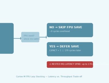
Variable penalties: If the FPU is enabled and lazy stacking is active, the initial entry latency is preserved at 12 cycles, but a penalty of 18-34 cycles is incurred later if the ISR executes a floating-point instruction. Unaligned stack pointers at exception entry can also add a 1 cycle penalty.
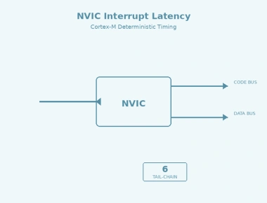
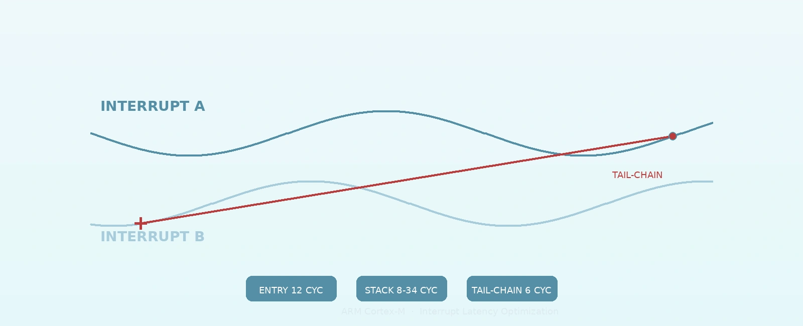
Tail-chaining eliminates the stacking/unstacking overhead when returning from an exception if there are pending interrupts. Instead of performing a full context restore to return to thread mode (or a lower-priority background ISR), the processor branches directly to the next pending ISR.
INTERRUPT A INTERRUPT B (Pending)+----------------------+ +----------------------+| Entry (12 cyc) | | || ISR Body | | || | TAIL-CHAIN | || BX LR (EXC_RETURN) | ----------> | (skipped context ops)|| Exit/Unstack (10 cyc)| (6 cyc) | ISR Body || | | BX LR || (Return to Thread) | | Exit/Unstack (10 cyc)|| B Entry (12 cyc) | | |+----------------------+ +----------------------+Standard overhead between ISRs: 22 cycles (Exit 10 + Entry 12)Tail-chain overhead: 6 cyclesTotal Savings: 16 cycles per chained interrupt
The tail-chain sequence takes only 6 cycles: the processor recognizes the pending interrupt during the current ISR’s exception return, fetches the new vector, and directly enters the next ISR—skipping the full unstack/restack cycle.
Critical condition: Tail-chaining occurs for pending interrupts that have a lower or equal logical priority (a higher or equal numerical group priority value) than the current ISR, which prevented them from preempting earlier. Subpriority does not affect preemption or tail-chaining eligibility.
void NVIC_ConfigPriorityGrouping(void) {// Configure 4 bits group priority, 4 bits subpriority (on 8-bit priority systems)// PRIGROUP = 3 (0b011). CMSIS handles the required VECTKEY write internally.NVIC_SetPriorityGrouping(3);}
With 4-bit group priority (16 levels), you can assign related peripherals to the same group priority but different subpriorities. This ensures they tail-chain rather than preempt each other:
// Get current grouping to ensure encoding matches hardware configurationuint32_t pg = NVIC_GetPriorityGrouping();// UART1 and UART2 at same group priority (3), different subpriorities// They will tail-chain when both fire, never preempt each otherNVIC_SetPriority(UART1_IRQn, NVIC_EncodePriority(pg, 3, 1)); // Group=3, Sub=1NVIC_SetPriority(UART2_IRQn, NVIC_EncodePriority(pg, 3, 2)); // Group=3, Sub=2// DMA at higher group priority (2) - will preempt UARTsNVIC_SetPriority(DMA1_Stream5_IRQn, NVIC_EncodePriority(pg, 2, 0)); // Group=2
Common mistake: Misunderstanding vendor HAL macros. For example, in STM32’s HAL, NVIC_PRIORITYGROUP_0 actually maps to a raw PRIGROUP value of 7, which assigns 0 bits to group priority. This disables preemption entirely—every interrupt runs to completion, meaning higher-urgency events cannot interrupt lower-urgency ones. Make sure you know whether you are configuring raw ARM registers or using a vendor abstraction layer.
Lazy stacking (enabled by default via FPCCR.LSPEN) is an optimization that prevents the FPU registers from being stacked during interrupt entry, preserving the 12-cycle entry latency.
The penalty (18-34 cycles) only occurs if the ISR actually executes a floating-point instruction. Thus, avoiding floating-point math in your most time-critical ISRs ensures they maintain the lowest possible latency without disabling FPU support globally.
The Cortex-M stack must be 8-byte aligned at exception entry. Misaligned stacks force the processor to adjust SP, adding a 1 cycle penalty:
// In startup code or linker script, ensure _estack is 8-byte aligned// .stack (ORIGIN(RAM) + LENGTH(RAM)) : ALIGN(8)// Or in C:__attribute__((aligned(8))) static uint8_t stack_buffer[4096];
__attribute__((interrupt))Unlike older ARM architectures, Cortex-M processors handle exception context saving and EXC_RETURN entirely in hardware using the standard AAPCS C calling convention.
// Correct: Use standard C functions for Cortex-M ISRsvoid DMA1_Stream5_IRQHandler(void) {// Handler body// Standard 'bx lr' return triggers hardware unstacking}
Using __attribute__((interrupt)) on Cortex-M is not only unnecessary but can degrade performance by causing the compiler to emit redundant stack-alignment instructions.
Use the cycle counter (DWT->CYCCNT) for cycle-accurate measurement. Crucially, you must capture the start time right before triggering the interrupt, and the end time as the very first operation inside the handler:
#define DWT_CTRL (*(volatile uint32_t*)0xE0001000)#define DWT_CYCCNT (*(volatile uint32_t*)0xE0001004)#define DWT_LAR (*(volatile uint32_t*)0xE0001FB0)#define DEMCR (*(volatile uint32_t*)0xE000EDFC)void DWT_Init(void) {DEMCR |= (1UL << 24); // Enable DWT#if (__CORTEX_M >= 7)DWT_LAR = 0xC5ACCE55; // Unlock DWT (required for Cortex-M7/M33)#endifDWT_CTRL |= (1UL << 0); // Enable cycle counter}volatile uint32_t trigger_cycles;volatile uint32_t isr_entry_cycles;void Trigger_Test_Interrupt(void) {trigger_cycles = DWT_CYCCNT;NVIC_SetPendingIRQ(EXTI0_IRQn); // Software trigger__DSB(); // Ensure trigger executes}void EXTI0_IRQHandler(void) {isr_entry_cycles = DWT_CYCCNT; // Must be first instruction!// ... ISR body ...}
Measure isr_entry_cycles - trigger_cycles. On Cortex-M4 at 168 MHz, expect exactly 12 cycles (71 ns) for integer-only ISRs from zero wait-state memory. Wait states (like executing from Flash) will increase this value.
| Technique | Latency Benefit | Note |
|---|---|---|
| Tail-chaining (same group priority) | Saves ~16 cycles per chained IRQ | Requires careful priority grouping |
| FPU lazy stacking (default) | Preserves 12-cycle entry | Penalty deferred to first FPU instruction |
| 8-byte stack alignment | Prevents 1 cycle penalty | Guaranteed by most modern linkers |
Avoid interrupt attribute | Avoids redundant compiler instructions | Cortex-M natively supports C functions |
| Priority grouping (4-bit group) | Enables tail-chaining | 16 preemption levels max |
The single most impactful optimization is priority grouping that enables tail-chaining for related interrupt sources. A UART+DMA pair at the same group priority will tail-chain reliably, saving ~16 cycles per transfer completion interrupt. For hard real-time deadlines, measure with DWT_CYCCNT—don’t rely on datasheet minimums.
Quick Links
Legal Stuff