

Fixing Zephyr Deep Sleep Backup SRAM Retention on STM32
September 12, 2026
4 min
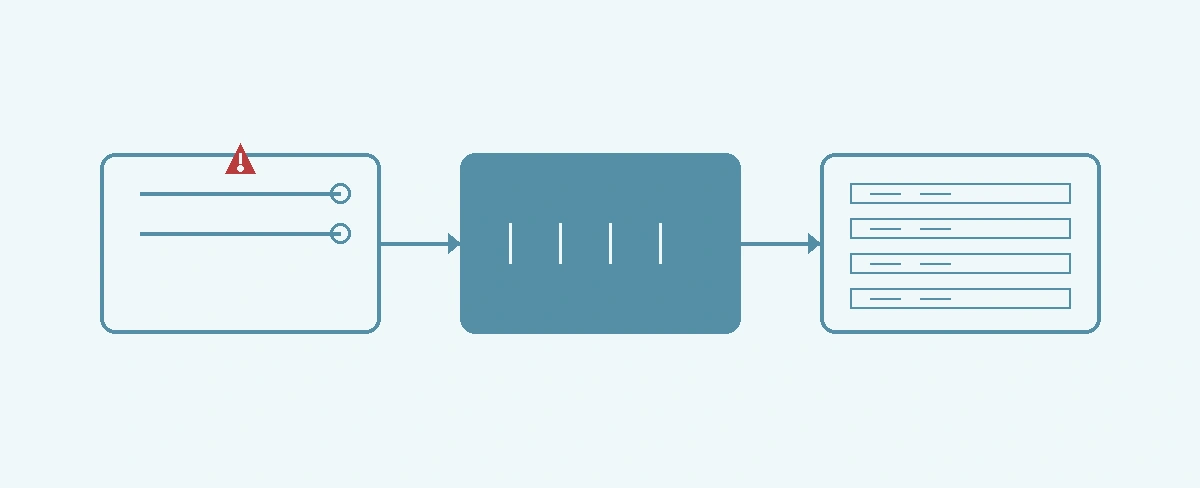
BMI160 SENSOR I2C BUS STM32 MCU┌─────────────────────┐ ┌─────────────────────┐ ┌─────────────────────┐│ SDA/SCL Lines │ │ Pull-up Resistors │ │ I2C Peripheral ││ 400kHz Max │ │ 4.7kΩ Standard │ │ Clock Config ││ │ │ │ │ ││ Chip ID: 0xD1 │──▶│ Rise Time Check │──▶│ Timeout Register ││ Soft Reset Reg │ │ ACK/NACK Monitor │ │ OVRE Flag │└─────────────────────┘ └─────────────────────┘ └─────────────────────┘│ │ ││ Clock Stretch │ Bus Analysis │ Driver Config│ Power Issues │ Logic Analyzer │ 400kHz Limit▼ ▼ ▼┌─────────┐ ┌─────────────┐ ┌─────────────┐│ TIMEOUT │ │ VERIFY: │ │ APPLY FIX: ││ ERROR! │ ───▶ │ 400kHz OK? │ ───▶ │ Reset Seq, │└─────────┘ │ Pull-ups? │ │ Power OK? ││ ACK Seen? │ └─────────────┘└─────────────┘
When integrating the Bosch BMI160 inertial measurement unit with an STM32 microcontroller using Zephyr’s I2C driver, developers often encounter intermittent I2C timeout errors. These timeouts manifest as failed register reads or writes, causing the sensor initialization to fail and disrupting data acquisition. This issue is particularly frustrating because it may occur sporadically, making root cause analysis challenging without systematic debugging.
The BMI160 specifies a maximum I2C clock frequency of 400kHz. If the STM32’s I2C peripheral is configured for a higher frequency (e.g., 1MHz), the BMI160 may not respond within the expected time window, leading to timeout errors.
The I2C bus requires pull-up resistors on both SDA and SCL lines. If the resistors are too large (e.g., 10kΩ) or missing, the bus rise time becomes too slow, especially at higher clock frequencies, causing the slave to miss clock pulses and timeout.
The BMI160 requires a stable power supply (typically 1.8V to 3.3V). Voltage fluctuations or insufficient current during sensor initialization can cause the device to hold the SCL line low (clock stretching) indefinitely, triggering a timeout in the master.
The BMI160 requires a specific reset sequence after power-up. Failing to follow the recommended reset procedure can leave the sensor in an undefined state, causing it to not respond to I2C commands.
Ensure that the I2C clock frequency is set to 400kHz or below for BMI160 compatibility. In Zephyr, this is configured in the device tree or via driver settings.
Use 4.7kΩ pull-up resistors for both SDA and SCL lines when operating at 400kHz. If the bus capacitance is high (due to long traces or multiple devices), consider reducing the resistor value to 3.3kΩ or 2.2kΩ, but ensure the sink current capability of the devices is not exceeded.
Add decoupling capacitors (0.1μF and 10μF) close to the BMI160’s VDD pin. Use a low-noise regulator or filter to ensure stable power during sensor initialization.
Follow the BMI160 datasheet’s recommended reset sequence: power on, wait for power-up time (typically 1ms), then issue a soft reset command via the appropriate register.
Below is a Zephyr device tree snippet and driver configuration for the BMI160 sensor on STM32, optimized to avoid I2C timeouts:
// devicetree.dts/ {i2c1: i2c@40013000 {status = "okay";clock-frequency = <I2C_BITRATE_FAST>; // 400kHzbmi160@68 {compatible = "bosch,bmi160";reg = <0x68>;label = "BMI160";};};};// prj.confCONFIG_I2C=yCONFIG_SENSOR=yCONFIG_BMI160=yCONFIG_BMI160_TRIGGER=y
And the corresponding sensor initialization in C:
// main.c#include <zephyr.h>#include <device.h>#include <drivers/sensor.h>void main(void){const struct device *bmi160 = device_get_binding("BMI160");if (!bmi160) {printk("Failed to get BMI160 device\n");return;}// Optional: Trigger a soft reset via register (if supported by driver)struct sensor_value reset_val = {0, 0};sensor_attr_set(bmi160, SENSOR_CHAN_ACCEL_XYZ,SENSOR_ATTR_RESET, &reset_val);// Give sensor time to resetk_msleep(10);// Now proceed with normal operationwhile (1) {struct sensor_value accel[3];sensor_sample_fetch(bmi160);sensor_channel_get(bmi160, SENSOR_CHAN_ACCEL_XYZ, accel);printk("Accel: %d.%06d, %d.%06d, %d.%06d\n",accel[0].val1, accel[0].val2,accel[1].val1, accel[1].val2,accel[2].val1, accel[2].val2);k_msleep(100);}}
After applying the fixes, verify the solution with the following steps:
Use an oscilloscope or logic analyzer to capture the I2C bus traffic during sensor initialization. Verify that:
Read the BMI160’s chip ID register (0x00) to confirm communication is working. The expected value is 0xD1.
Verify that the sensor provides valid accelerometer and gyroscope data within expected ranges.
Run the sensor continuously for extended periods (e.g., 24 hours) to ensure no intermittent timeouts occur.
Debugging I2C timeout issues with the Zephyr BMI160 driver on STM32 requires a holistic approach addressing clock configuration, bus integrity, power stability, and proper sensor initialization. By ensuring the I2C clock is set to 400kHz or below, using appropriate pull-up resistors, stabilizing the power supply, and following the recommended reset sequence, developers can eliminate timeout errors and achieve reliable sensor communication. Systematic verification with bus analysis and register validation confirms the fix and prevents regression.
Q: What causes I2C timeout in Zephyr’s BMI160 driver on STM32? A: I2C timeout in Zephyr’s BMI160 driver on STM32 is typically caused by incorrect clock configuration, missing pull-up resistors, or sensor not responding due to power issues.
Q: How to check I2C bus signals for BMI160 communication? A: Use an oscilloscope or logic analyzer to check SDA and SCL lines for proper voltage levels, acknowledge bits, and clock stretching during BMI160 register reads.
Q: What software fixes resolve I2C timeout in Zephyr BMI160 driver? A: Ensure correct I2C clock rate (400kHz for BMI160), add delays in driver initialization, and verify sensor power supply and reset sequencing.
Quick Links
Legal Stuff