

A/B vs In-Place Firmware Updates: Trade-offs for Embedded Systems
August 03, 2026
4 min
Technical writing is not a soft skill — it is a force multiplier for embedded and safety-critical engineering teams. Every hour spent writing clear documentation saves ten hours of debugging, onboarding, regulatory auditing, and rework. Yet many embedded engineers treat documentation as an afterthought, producing brief README files that explain how to compile code but not how the system works, why decisions were made, or how it behaves under failure modes.
This article covers practical patterns for writing embedded and safety-critical technical documentation that engineers and auditors actually read, trust, and verify.
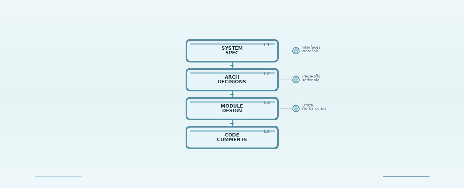
Embedded projects require four distinct layers of documentation, each serving a specific audience, abstraction level, and verification purpose:
+-------------------------------------------------------------------+| DOCUMENTATION LAYERS |+-------------------------------------------------------------------+| || L1 SYSTEM & SAFETY SPECIFICATION <- Architect, Safety Engineer || - System & safety requirements (ISO 26262 / IEC 61508) || - Interfaces, protocols, safety goals, ASIL/SIL targets || - Bidirectional requirements traceability & V&V criteria || || L2 ARCHITECTURE DECISION LOG <- Tech Lead, Systems Lead || - Why we chose MCU / RTOS / memory map / safety mechanisms || - Freedom From Interference (FFI) & MPU partitioning || - Trade-offs considered, alternatives rejected || || L3 MODULE DESIGN & HSI DOCS <- Implementer, Verifier || - Register maps, state machines, ISR latency budgets || - Hardware-Software Interface (HSI) contracts & protocols || - Unit & Hardware-in-the-Loop (HIL) test strategies || || L4 CODE-LEVEL & SAFETY COMMENTS <- Maintainer, Auditor || - Explains 'why' behind register bits & timing constraints || - Silicon errata workarounds tagged with silicon revision || - MISRA compliance deviations & cycle-budget annotations || |+-------------------------------------------------------------------+
Most teams only produce L4 (scattered comments) and call it done. The missing upper layers are where integration bugs, race conditions, and compliance failures hide.
An Architecture Decision Record (ADR) captures a significant technical choice with its context, rationale, and consequences. Keep them lightweight — one Markdown file per decision, stored in docs/adr/ with sequential numbering.
In safety-critical systems, ADRs serve as evidence for why specific safety mechanisms, memory protection layouts, or synchronization primitives were selected over alternatives.
# ADR-0042: Use FreeRTOS Stream Buffers for UART DMA Reception## StatusAccepted## ContextWe need high-throughput UART reception (up to 4 Mbps) on STM32H743VI with minimal CPU overhead. Options considered:1. Interrupt-per-byte with ring buffer → CPU saturation at high baud rates.2. DMA + circular buffer + idle-line detection → Complex ISR handling, fragile timing window.3. FreeRTOS Stream Buffers + DMA → Direct task notification, optimized thread-safe IPC.## DecisionUse Option 3. Stream buffers accept variable-length writes from ISR context via `xStreamBufferSendFromISR()` and notify the consumer task directly without mutex overhead.## Consequences- Requires FreeRTOS V10.0.0+ (Stream Buffer API introduction).- Data is passed by light copy into stream buffer memory (not zero-copy; for zero-copy DMA, direct task notification with double-buffered pointer swapping is required).- DMA HT (Half-Transfer) and TC (Transfer-Complete) interrupts feed stream buffer.- Consumer task blocks on `xStreamBufferReceive()` with a configurable timeout.- Memory allocation: 4 KB stream buffer + 2 KB DMA buffer per UART interface.## References- FreeRTOS Stream Buffer API: https://www.freertos.org/RTOS-stream-buffers.html- STMicroelectronics STM32H7 DMA + UART Application Note: AN4882
Rule: Every architectural decision affecting hardware interfaces, memory layout, RTOS configuration, fault tolerance, or third-party integration gets an ADR.
When writing device drivers or register-level interface code, document each register configuration with a clear table or structured block comment. The following C example demonstrates STM32H7 I2C timing configuration for 400 kHz Fast Mode:
/* I2C_TIMINGR register configuration for 400 kHz Fast Mode* MCU Variant: STM32H743VI, PCLK1 = 120 MHz, I2C Clock (I2CCLK) = 120 MHz* Datasheet: ST Reference Manual RM0433 Rev 8, Section 53.4.9* Silicon Errata: ES0392 Rev 7, Section 2.14.1 (I2C analog filter delay) */typedef struct {uint32_t presc; // PRESC[3:0] - Clock prescaler: t_PRESC = (PRESC + 1) * t_I2CCLKuint32_t scldel; // SCLDEL[3:0] - Data setup time: t_SCLDEL = (SCLDEL + 1) * t_PRESC (t_SU_DAT)uint32_t sdadel; // SDADEL[3:0] - Data hold time: t_SDADEL = SDADEL * t_PRESC (t_HD_DAT)uint32_t sclh; // SCLH[7:0] - SCL high period: t_SCLH = (SCLH + 1) * t_PRESCuint32_t scll; // SCLL[7:0] - SCL low period: t_SCLL = (SCLL + 1) * t_PRESC} I2C_Timing_t;/* Prescaler: PRESC = 1 -> f_PRESC = 120 MHz / (1 + 1) = 60 MHz (t_PRESC = 16.67 ns)* Setup time (SCLDEL = 4): (4 + 1) * 16.67 ns = 83.33 ns (+ analog filter delay = ~110 ns, t_SU_DAT min 100 ns)* Hold time (SDADEL = 2): 2 * 16.67 ns = 33.33 ns (t_HD_DAT min 0 ns)* SCL High (SCLH = 53): (53 + 1) * 16.67 ns = 900 ns (0.9 us, t_HIGH min 0.6 us)* SCL Low (SCLL = 95): (95 + 1) * 16.67 ns = 1600 ns (1.6 us, t_LOW min 1.3 us)* Total SCL period: (54 + 96) * 16.67 ns = 150 * 16.67 ns = 2.50 us -> Exact 400.0 kHz */const I2C_Timing_t I2C_TIMING_400KHZ = {.presc = 0x1, // 60 MHz prescaled clock (t_PRESC = 16.67 ns).scldel = 0x4, // 5 cycles = 83.3 ns setup time (t_SU_DAT).sdadel = 0x2, // 2 cycles = 33.3 ns hold time (t_HD_DAT).sclh = 0x35, // 54 cycles high = 900 ns (0.9 us).scll = 0x5F, // 96 cycles low = 1600 ns (1.6 us)};/* Computed 32-bit register value conforming to STM32 I2C_TIMINGR bit layout:* Bits [31:28] = PRESC, Bits [23:20] = SCLDEL, Bits [19:16] = SDADEL,* Bits [15:8] = SCLH, Bits [7:0] = SCLL */#define I2C_TIMINGR_VALUE (((uint32_t)(I2C_TIMING_400KHZ.presc) << 28) | \((uint32_t)(I2C_TIMING_400KHZ.scldel) << 20) | \((uint32_t)(I2C_TIMING_400KHZ.sdadel) << 16) | \((uint32_t)(I2C_TIMING_400KHZ.sclh) << 8) | \((uint32_t)(I2C_TIMING_400KHZ.scll) << 0))
Key Elements of High-Quality Register Documentation:
SCLDEL) vs hold time (SDADEL).The most expensive bugs in embedded development occur at the hardware-software boundary. In ISO 26262 and DO-178C workflows, the Hardware-Software Interface (HSI) specification is a mandatory work product.
# HW-SW Contract: ADC1 + DMAMUX1/DMA2 + FreeRTOS Task (STM32H7)## Signal ChainADC1 (16-bit) → DMAMUX1 → DMA2 Stream 0 (circular, half/transfer complete IRQ) → FreeRTOS Task (Priority 6)## Timing Requirements (ADC clock = 36 MHz)| Parameter | Symbol | Min | Typ | Max | Unit | Notes ||--------------------|----------|------|------|------|------|------------------------------------------|| Sample rate | f_s | - | 100 | - | kSPS | 100 kSPS per channel (2 channels total) || Conversion time | t_conv | - | 0.36 | 0.50 | µs | 16-bit: 4.5 sampling + 8.5 conv = 13 cyc || DMA transfer time | t_dma | - | 0.8 | 1.0 | µs | 16-bit × 2 ch, 16-beat burst || Task wake latency | t_wake | - | 2.1 | 3.5 | µs | FreeRTOS context switch + D-cache inv || End-to-end latency | t_e2e | - | 3.3 | 5.0 | µs | Sample completion to task start |## Memory & Cache Buffer Contract- DMA buffer: 2 × 1024 `uint16_t` (ping-pong), aligned to 32 bytes (`__attribute__((aligned(32)))`) for Cortex-M7 D-cache line compatibility.- Half-Transfer (HT) IRQ → Notify task to process first half; call `SCB_InvalidateDCache_by_Addr()` prior to buffer read.- Transfer-Complete (TC) IRQ → Notify task to process second half; call `SCB_InvalidateDCache_by_Addr()` prior to buffer read.- Processing deadline: Task MUST complete processing each half within 5.12 ms (200 kSPS total throughput = 5.12 ms filling time per 1024-sample half).## Error Handling & Diagnostic Coverage| Condition | Detection Mechanism | Action / Safe State ||------------------------|---------------------|------------------------------------------|| DMA transfer error | DMA TEIF flag | Assert, log event, re-initialize DMA || ADC overrun | ADC OVR flag | Flag diagnostic fault, increment counter || Task overrun (missed) | Sequence counter gap| Discard stale frame, enter safe state |## Power & Initialization Sequencing1. Enable ADC clock in RCC.2. Perform ADC self-calibration (single-ended & differential modes).3. Configure DMAMUX1 routing and DMA2 Stream 0 (circular mode, HT/TC IRQs enabled).4. Create consumer FreeRTOS task.5. Enable DMA stream and start ADC conversions (timer-triggered).## Verification Checklist- [ ] Monitor ADC EOC, DMA IRQ, and task toggle pins on logic analyzer.- [ ] Verify zero sample loss at 100 kSPS/channel over 24-hour continuous run.- [ ] Inject DMA transfer error → Verify diagnostic interrupt fires and logs correctly.- [ ] Inject ADC overrun → Verify error counter increments and safe state logic executes.
Rule: Never rely on verbal agreements for hardware-software boundaries. Document them as formal contracts before writing driver or application logic.
For localized design choices that do not require a full ADR but would confuse future maintainers, use a standardized decision comment block:
/* DECISION: Use LPTIM1 for system tick instead of SysTick* REASON: SysTick halts in System Stop mode; LPTIM1 continues running off LSE (32.768 kHz) in D1/D2/D3 System Stop modes.* TRADE-OFF: LPTIM1 tick resolution is 30.5 µs (32.768 kHz) vs SysTick 2.08 ns (480 MHz).* ALTERNATIVES: SysTick + RTC wake-up timer (rejected due to higher wake latency and power state transitions).* REFERENCE: ST RM0433 Sec 41 (LPTIM), FreeRTOS tickless idle porting guide* AUTHOR: jtom, 2026-03-15*/
Format standard: DECISION, REASON, TRADE-OFF, ALTERNATIVES, REFERENCE, AUTHOR, DATE. This structure is easily greppable and actionable during code reviews.
For engineers developing systems subject to functional safety standards (ISO 26262 for automotive, IEC 61508 for industrial, DO-178C for aerospace, IEC 62304 for medical), documentation is an essential part of the safety case.
Safety standards require full traceability from top-level safety goals down to individual lines of code and test cases:
System Safety Requirement (SSR-102)└── Software Safety Requirement (SWR-204)└── Software Architecture Component (ARCH-CAN-01)└── Module Design & Source Code (can_driver.c:L142)└── Unit Test Case (test_can_rx_timeout())
In technical documentation and code comments, reference requirement identifiers explicitly:
/* Implements SWR-204 [ASIL-C]: Verify CAN bus-off recovery timer* Safety Goal: SG-03 (Prevent unannounced loss of CAN communication) */void CAN_CheckBusOffRecovery(void) {// ...}
When writing safety-critical design docs, specify:
When code must deviate from standards like MISRA C:2012 / MISRA C:2023, document the deviation inline with justification:
/* MISRA C:2012 Rule 11.4 Deviation* Justification: Hardware memory-mapped register access requires casting integer address to volatile pointer.* Verification: Address verified against ST RM0433 memory map Section 2.3. */#define I2C1_BASE_ADDR ((I2C_TypeDef *) 0x40005400U)
# Quick Start: STM32H743VI + FreeRTOS + LwIP## Hardware Required- Custom Board Rev B3 or later (Rev B2 has PHY reset bug; see ERR-007)- ST-LINK/V3 or J-Link OB debugger- 12V / 2A DC supply, Ethernet cable## First Boot Procedure (5 minutes)1. Connect ST-LINK debugger and apply 12V power.2. Launch OpenOCD server:`openocd -f interface/stlink.cfg -f target/stm32h7x.cfg`3. In a separate terminal, launch GDB:`arm-none-eabi-gdb build/firmware.elf`4. Connect GDB to OpenOCD session:`(gdb) target extended-remote :3333``(gdb) load``(gdb) monitor reset halt``(gdb) continue`## Verification Steps- Green LED (PD13) blinks at 1 Hz → FreeRTOS system tick is running.- Blue LED (PD15) solid ON → LwIP stack initialized, DHCP IP acquired.- Host ping test: `ping <board-ip>` → Ethernet communication verified.## Known Hardware & Silicon Issues| Issue | Workaround | Target Fix ||--------------------------------------|----------------------------------------------|-----------------|| PHY reset fails on cold power-up | Cycle 12V main power supply | Board Rev B4 || ADC calibration hangs if VDDA < 2.7V | Verify power rail before calling calibration | Firmware v2.1.0 |
## Known Issues: I2C Driver (i2c_stm32h7.c)| ID | Description | Workaround | Status ||--------|-----------------------------------------------------------|--------------------------------------------------------------|-----------------------|| I2C-01 | Clock stretching timeout at 400 kHz with legacy slave ICs | Reduce clock to 100 kHz or implement bit-bang fallback | Open (Hardware limit) || I2C-02 | Bus busy flag stuck after arbitration loss | Execute software reset of I2C peripheral + GPIO clock toggle | Fixed (v1.3.0) || I2C-03 | DMA TX complete flag sets before final byte is on wire | Add 2-byte dummy buffer padding for DMA transfers | Verified (v1.4.0) |
## Integration Test: UART DMA + FreeRTOS Stream Buffer### Setup- Target Board: STM32H743VI Custom Board Rev B3- PC Interface: USB-to-UART Adapter (FT232H), 4 Mbps, 8N1- Test Script: `scripts/uart_stress.py`### Procedure1. Flash `firmware_uart_dma_test.elf` to target board.2. Run test script on host PC:`python3 scripts/uart_stress.py --port /dev/ttyUSB0 --baud 4000000 --duration 60`3. Monitor performance metrics and logic analyzer output.### Pass Criteria| Metric | Target Constraint | Measured Result ||-----------------|-------------------|-----------------|| Throughput | ≥ 3.8 Mbps | 3.92 Mbps || CPU Utilization | ≤ 15% | 11.4% || Buffer Overruns | 0 in 60 seconds | 0 || CRC Error Rate | 0 | 0 |
| Anti-Pattern | Why It Fails | Better Approach |
|---|---|---|
| “See datasheet” comments | Reference manuals exceed 2000 pages; context is lost | Cite exact section, register name, and bit-field |
| Documenting “what”, not “why” | Source code already shows what happens | Document timing constraints, silicon errata, and trade-offs |
| README-only documentation | README explains build commands, not architecture | Hierarchy: System Spec → ADR → HSI Contract → Code Comments |
| Outdated comments | Outdated documentation causes severe debugging delays | Enforce comment reviews in PRs; remove invalid comments |
| Omitting hardware context | Software maintainers lack hardware schematics | Include pin maps, memory layouts, and power-up sequences |
| Missing safety traceability | Audits fail due to unlinked requirements | Tag code and design blocks with requirement IDs (e.g., SWR-101) |
markdownlint-cli) — Enforce heading hierarchy, line lengths, and consistent formatting in CI/CD pipelines.Effective technical writing in embedded and safety-critical engineering is not about writing long documents — it is about precision at the hardware-software boundary.
The four-layer hierarchy (System Spec → ADR → Module Design / HSI → Code Comments) ensures that developers, architects, and compliance auditors find exact information at the right level of abstraction. Register tables with explicit formulas prevent bit-manipulation bugs. HSI contracts with timing and cache rules eliminate integration failures. ADRs and inline decision logs preserve design rationale for future maintainers.
Start small:
Treat technical writing as an essential engineering discipline, and it will compound in value across the entire lifecycle of your embedded system.
Quick Links
Legal Stuff